Email: sales@telsto.cn
 Telephone: 86-021-6221 2832
 LinkedIn
 Youtube
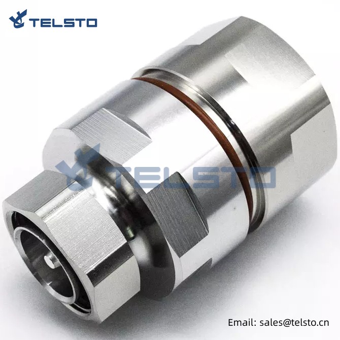
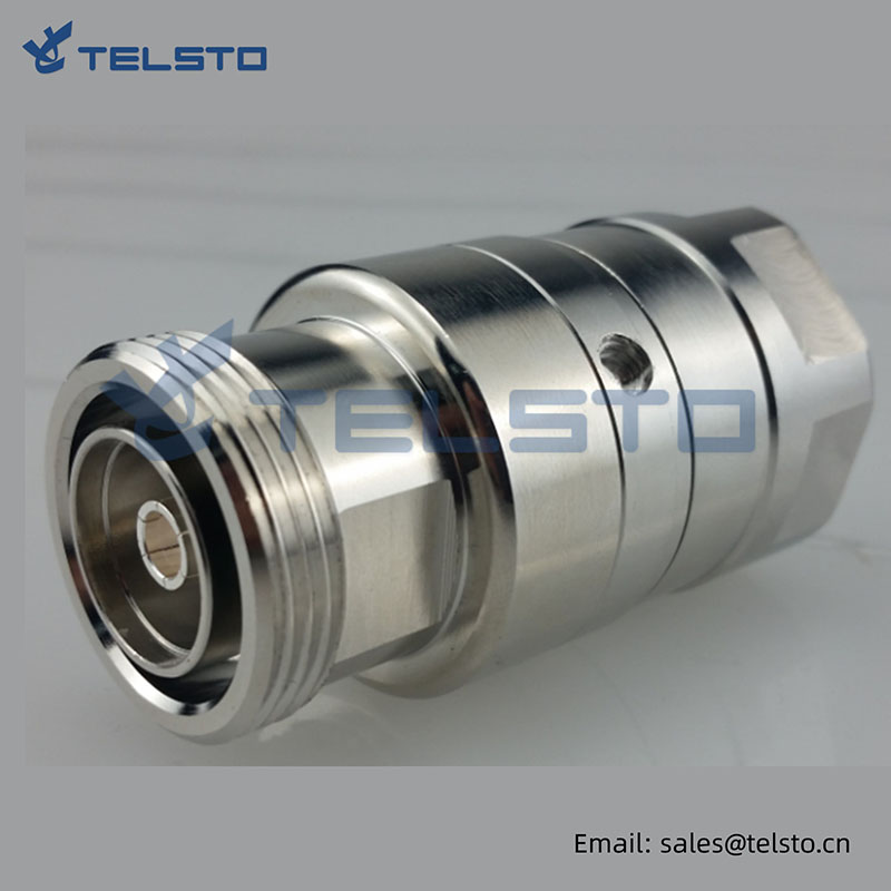
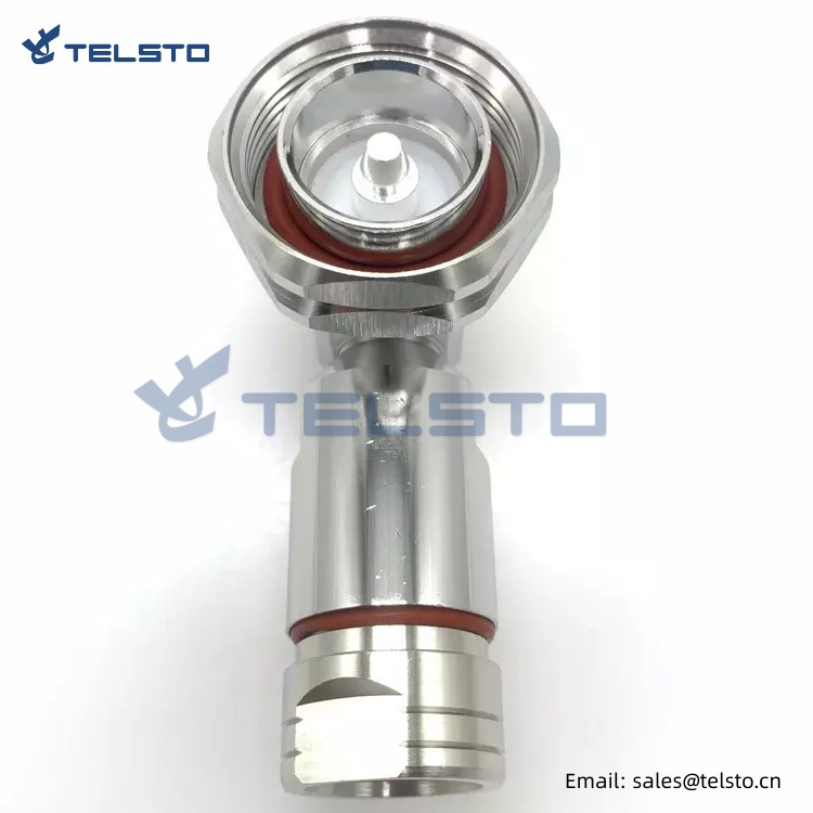
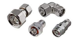
7/16 male connector for 1-1/4″ cable
1. Our product is 7/16 type (L29) thread-coupled RF coaxial connector. The characteristic impedance of this connector is 50 Ohms, which has the characteristics of high power, low VSWR, small attenuation, small intermodulation and good air tightness.
First of all, our 7/16 (L29) thread-coupled RF coaxial connector has extremely high power carrying capacity, which can carry up to 2 kW of power. This means that it can work stably and reliably in high-power applications without worrying about signal interruption or distortion.
2. Secondly, our connector has very low VSWR, that is, voltage standing wave ratio. This means that it can provide high-quality signal transmission while reducing signal reflection and loss, thus ensuring the accuracy and stability of the signal.
3. In addition, our connector has low attenuation, which means that it can provide very low signal attenuation, so as to maximize the strength and stability of the signal. In addition, our connector has small intermodulation, which means that it can effectively reduce the interference and distortion between different frequency signals, thus ensuring the accuracy and stability of the signal.
4. Finally, our connector has excellent airtight performance, which means it can work in harsh environment, such as high temperature, high humidity, high pressure, etc. At the same time, it can also protect the inside of the connector from the impact of external environment, thus extending its service life
| 7/16 Din Male Connector For 1-1/4" Foam Feeder Cable | ||
| Model No. | TEL-DINM.114-RFC | |
| Interface | IEC 60169-4;DIN-47223;CECC-22190 | |
| Electrical | ||
| Characteristic Impedance | 50ohm | |
| Frequency Range | DC-7.5GHz | |
| VSWR | ≤1.20@DC-3000MHz | |
| 3rd Order IM (PIM3) | ≤ -155dBc@2×20W | |
| Dielectric Withstanding Voltage | ≥4000V RMS,50Hz,at sea level | |
| Dielectric Resistance | ≥10000MΩ | |
| Contact Resistance | Center Contact ≤0.4mΩ | Outer Contact ≤1 mΩ |
| Mating | M29*1.5 threaded coupling | |
| Mechanical | ||
| Durability | Mating cycles ≥500 | |
| Material and Plating | ||
| Parts Name | Material | Plating |
| Body | Brass | Tri-Metal(CuZnSn) |
| Insulator | PTFE | — |
| Inner Conductor | Phosphor Bronze | Ag |
| Coupling Nut | Brass | Ni |
| Gasket | Silicone Rubber | — |
| Cable Clamp | Brass | Ni |
| Ferrule | — | — |
| Environmental | ||
| Operating Temperature | -45 ℃ to 85 ℃ | |
| Weatherproof Rate | IP67 | |
| RoHs (2002/95/EC) | Compliant by exemption | |
| Suitable Cable Family | 1-1/4'' feeder cable | |
Related
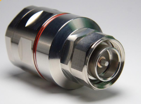
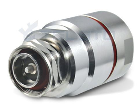
Model: TEL-DINM.114-RFC
Description
DIN Male connector for 1-1/4″ feeder cable
| Material and Plating | |
| Center contact | Brass / Silver Plating |
| Insulator | PTFE |
| Body & Outer Conductor | Brass / alloy plated with tri-alloy |
| Gasket | Silicon Rubber |
| Electrical Characteristics | |
| Characteristics Impedance | 50 Ohm |
| Frequency Range | DC~3 GHz |
| Insulation Resistance | ≥10000MΩ |
| Dielectric Strength | 4000 V rms |
| Center contact resistance | ≤0.4mΩ |
| Outer contact resistance | ≤1.5 mΩ |
| Insertion Loss | ≤0.12dB@3GHz |
| VSWR | ≤1.15@-3.0GHz |
| Temperature range | -40~85℃ |
| Waterproof | IP67 |
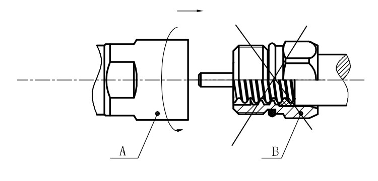
Installation Instructions of N or 7 / 16 or 4310 1 / 2″ super flexible cable
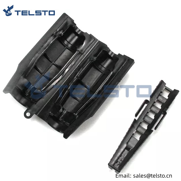
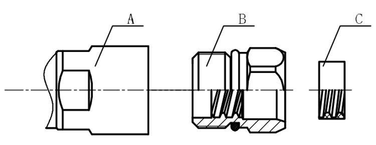
Structure of connector: ( Fig1 )
A. front nut
B. back nut
C. gasket
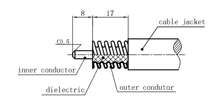
Stripping dimensions is as shown by diagram ( Fig2 ), attention should be paid while stripping:
1. The end surface of inner conductor should be chamfered.
2. Remove impurities such as copper scale and burr on the end surface of the cable.
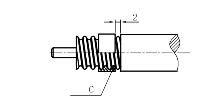
Assembling the sealing part: Screw the sealing part in along the outer conductor of the cable as shown by the diagram ( Fig3).
Assembling the back nut (Fig3).
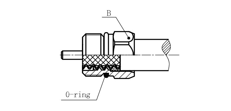
Combine the front and back nut by screwing as shown by diagram ( Figs( 5)
1. Before screwing, smear a layer of lubricating grease on the o-ring.
2. Keep the back nut and the cable motionless, Screw on main shell body on back shell body. Screw down main shell body of back shell body using monkey wrench. Assembling is finished.