 Email: sales@telsto.cn
 Telephone: 86-021-6221 2832
 LinkedIn
 Youtube
Reliable RF transmission depends on more than selecting the right antenna or radio equipment. The coaxial cable connecting these components also plays a direct role in signal loss, impedance stability, interference protection, and overall system performance.
For many wireless and RF installations, TEL400 cable is a commonly selected 50-ohm coaxial cable because it offers a practical balance between relatively low attenuation, mechanical flexibility, shielding performance, and ease of installation.
It is widely used in telecom infrastructure, distributed antenna systems, Wi-Fi networks, GPS systems, radio equipment, test systems, and other RF signal transmission applications.
However, selecting an TEL400 coaxial cable should not be based on cable name alone. Engineers and procurement teams also need to evaluate cable construction, operating frequency, attenuation, installation environment, jacket material, cable length, and connector compatibility.
This guide explains how TEL400 cable is constructed, how its key performance characteristics affect RF systems, where it is commonly used, and what should be considered when matching it with RF connectors.
.jpg)
What Is TEL400 Cable?
TEL400 is a type of 50-ohm coaxial cable designed for RF signal transmission.
Like other coaxial cables, it contains a center conductor surrounded by dielectric insulation, shielding layers, and an outer protective jacket. This concentric construction helps maintain controlled impedance while reducing signal leakage and interference from external electromagnetic sources.
TEL400-type cables are commonly selected where an RF installation needs lower signal loss than smaller-diameter coaxial cables while still requiring a cable that is practical to route and terminate.
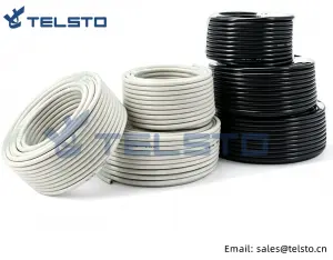
The Telsto 50-ohm braided coaxial cable range includes TEL300, TEL400, TEL500, TEL600, TEL900 and other RF cable configurations. The series is designed around a nominal 50-ohm RF system and is intended for telecommunications, broadcasting, wireless networks, and RF signal interconnection.
One important point is that TEL400 and RG8/U should not automatically be treated as completely interchangeable specifications.
Although some suppliers group TEL400 and RG8/U-type cables together because of similarities in general size or application, construction details, attenuation, shielding, jacket materials, and connector requirements can differ between manufacturers. Engineers should therefore confirm the actual cable datasheet before replacing one cable type with another.
How Is TEL400 Cable Constructed?
The performance of an RF coaxial cable is strongly influenced by its internal construction.
A typical TEL400-style cable includes five main elements:
- Center conductor
- Dielectric insulation
- Foil shielding
- Braided shielding
- Outer jacket
Each layer performs a different function in maintaining electrical and mechanical performance.
1. Center Conductor
The center conductor carries the RF signal through the cable.
Its material, diameter, and conductivity influence insertion loss, power handling, and overall electrical performance.
For RF applications, conductor quality is important because signal loss increases as frequency rises. A well-controlled conductor structure helps maintain predictable performance throughout the cable length.
When selecting cable for a specific project, engineers should also consider whether the installation requires repeated bending or relatively fixed routing, because conductor design can influence cable flexibility.
2. Foam Polyethylene Dielectric
The dielectric layer separates the center conductor from the outer shielding system.
In Telsto’s TEL/RG coaxial cable series, gas-injected foam polyethylene (PE) is used as the dielectric material. Compared with a dense solid dielectric, a properly designed foam structure can help reduce dielectric losses and support improved signal transmission, particularly as operating frequency and cable length increase.
The dielectric also plays an important role in maintaining the correct spacing between the inner and outer conductors.
That spacing is essential for maintaining the characteristic impedance of the cable.
For most telecom and wireless RF systems using this cable class, that target impedance is 50 ohms.
3. Bonded Aluminum Foil Shield
The first shielding layer typically consists of aluminum foil surrounding the dielectric.
The foil helps provide continuous shielding coverage and reduces RF energy leakage from the cable.
It also helps protect the transmitted signal from electromagnetic interference generated by nearby electrical equipment, power systems, radio equipment, and other RF sources.
This becomes particularly important in dense telecom sites where multiple cables and active systems may operate in close proximity.
4. Braided Shield
Outside the foil layer is a metallic braid.
Telsto’s corresponding coaxial cable series combines bonded aluminum foil with tinned copper or aluminum-alloy braiding, with the product information specifying braid coverage in the 80%–95% range. This dual-layer shielding structure is intended to improve protection against EMI and RFI.
The braid provides both electrical shielding and mechanical support.
Higher-quality shielding can be especially important in installations where signal integrity must be maintained in electrically noisy environments.
However, shielding effectiveness should always be evaluated together with connector installation. Even a well-shielded cable can experience performance problems if the connector termination is poorly prepared or incorrectly assembled.
5. Outer Jacket
The cable jacket protects the internal structure from mechanical damage and environmental exposure.
Different jacket materials are appropriate for different installation environments.
Telsto’s current coaxial cable range provides options including PVC, PE, and LSZH jackets.
PVC is commonly considered for general-purpose installations.
PE jackets are often preferred for outdoor applications where greater resistance to weather and ultraviolet exposure may be required.
LSZH, or Low Smoke Zero Halogen, jackets are used in applications where fire safety requirements place greater emphasis on reducing smoke and halogen emissions.
The jacket should therefore be selected according to the actual project environment rather than simply choosing the lowest-cost option.
Key Performance Characteristics of TEL400 Cable
When comparing TEL400 cable options, several electrical characteristics deserve particular attention.
50-Ohm Characteristic Impedance
Most RF telecommunications systems are designed around a 50-ohm impedance.
Maintaining consistent impedance throughout the cable, connector, adapter, and equipment interface helps reduce reflections and supports efficient RF power transfer.
Telsto specifies a characteristic impedance of 50±2 ohms for its related braided coaxial cable series.
Impedance mismatch can increase reflected energy and negatively affect VSWR, so a cable should not be evaluated independently from the connectors and equipment used with it.
Attenuation
Attenuation describes how much RF signal power is lost as the signal travels through the cable.
It is usually expressed in decibels over a specified cable length and frequency.
In practical installations, attenuation typically increases with:
- Higher operating frequency
- Longer cable length
- Smaller conductor size
- Less efficient dielectric construction
- Poor connector installation
- Damaged or sharply bent cable
This means the same cable may be entirely suitable for a short RF jumper but less suitable for a much longer feeder run at a higher frequency.
Engineers should therefore evaluate attenuation at the actual operating frequency and required cable length, rather than relying only on a general description such as “low-loss cable.”
VSWR
Voltage Standing Wave Ratio, or VSWR, indicates how effectively RF energy is transmitted through a system without excessive reflection.
Cable quality is one factor affecting VSWR, but connectors, adapters, antenna interfaces, and installation workmanship also contribute.
For this reason, a low-VSWR cable does not automatically guarantee a low-VSWR assembled system.
The entire RF path needs to be considered.
Shielding Effectiveness
RF installations often operate near other transmitters, electrical equipment, power cables, or communication systems.
Proper shielding helps prevent external interference from entering the cable and reduces unwanted signal radiation from the cable itself.
The combination of foil and braid shielding makes TEL400-style coaxial cables suitable for many RF environments where signal integrity matters.
Environmental Performance
Temperature, moisture, ultraviolet radiation, vibration, and mechanical stress can all affect cable reliability.
Telsto specifies an operating temperature range of -40°C to +85°C for its corresponding braided coaxial cable series.
Actual project selection should also consider installation location, exposure conditions, cable routing, sealing methods, and local engineering requirements.
Where Is TEL400 Cable Commonly Used?
Because TEL400 cable provides a useful balance between RF performance and installation practicality, it can be applied across a wide range of communication systems.
Cellular and Wireless Infrastructure
TEL400-type coaxial cable may be used to connect antennas, RF devices, radio equipment, and associated components in wireless infrastructure.
Applications can include 4G LTE systems, 5G-related installations, small wireless sites, and other RF communication networks.
For longer or higher-power feeder runs, however, engineers may need to compare TEL400 with larger feeder cables to determine whether attenuation and power-handling requirements can be met.
Distributed Antenna Systems
Distributed Antenna Systems, or DAS, use multiple antennas to improve wireless coverage across buildings, transportation facilities, campuses, industrial sites, and other environments.
Coaxial cables are used to carry RF signals between system components.
The appropriate cable size depends on the distance, operating frequency, acceptable system loss, and installation space.
Wi-Fi and Wireless Networks
External antennas, access points, radio equipment, and wireless bridges may require coaxial cable connections.
Where cable runs are longer than standard short RF jumpers, using a lower-loss cable such as TEL400 can help reduce transmission losses.
GPS and Satellite Communication
GPS antennas and satellite-related equipment often require reliable RF connections between outdoor antennas and indoor electronics.
Cable attenuation becomes particularly important because received signals can be relatively weak.
Cable length and frequency should therefore be carefully evaluated during system design.
Two-Way Radio Systems
TEL400 cable is also used in two-way radio installations, including commercial radio systems, public-safety communications, industrial radio networks, and other land-mobile applications.
In these systems, proper cable and connector selection helps minimize unnecessary RF loss between the radio equipment and antenna.
Broadcast and Test Systems
Broadcasting, laboratory testing, equipment interconnection, and RF measurement setups may also use 50-ohm coaxial cable.
The decision depends on the frequency range, required flexibility, connector interface, and acceptable insertion loss.
Telsto identifies telecommunications, wireless networks, broadcasting, GPS/satellite-related systems, and test and measurement among the application areas for its corresponding coaxial cable series.
What Connectors Are Compatible with TEL400 Cable?
Selecting the correct RF connector is just as important as selecting the cable itself.
A connector should match:
- Cable diameter
- Inner and outer conductor dimensions
- Cable construction
- Characteristic impedance
- Operating frequency
- Installation method
- Environmental requirements
- Equipment interface
One commonly used interface with TEL400-type cable is the N-Type connector.
N-Type connectors are widely used in telecommunications, antenna systems, base stations, wireless infrastructure, and RF test equipment because they provide a threaded mechanical connection and are available for a variety of coaxial cable constructions.
Telsto offers an N male clamp-type RF connector intended for RG8/RG213/TEL400-class cable applications. The product is designed around a 50-ohm RF interface and uses a clamp-style cable termination.
Other connector families may also be used depending on the equipment interface and system design.
For modern wireless infrastructure, 4.3-10 connectors are commonly encountered because of their compact format and suitability for low-PIM RF systems.
However, engineers should not select a connector simply because the interface type is technically compatible with the radio equipment.
The connector must also be specifically designed for the cable being terminated.
An N-Type connector for one cable diameter may not correctly fit another 50-ohm coaxial cable even though both cables have the same nominal impedance.
How to Select TEL400 Cable for an RF Project
For engineers and purchasing teams, a practical selection process should begin with the complete application rather than the cable name.
Consider the following factors before specifying TEL400 cable.
Operating Frequency
Determine the highest frequency the system will use.
Attenuation increases with frequency, so performance should be checked at the actual operating frequency rather than at a lower reference frequency.
Cable Length
A cable that performs well over a short run may introduce excessive loss over a long run.
Estimate total cable length and calculate the expected RF loss before final selection.
Connector and adapter losses should also be included where necessary.
Acceptable System Loss
RF link budgets often specify how much loss can be tolerated between equipment and antenna.
Cable attenuation should be evaluated within this total loss budget.
Installation Environment
Determine whether the cable will be installed:
- Indoors
- Outdoors
- Inside cabinets
- Along telecom towers
- In public buildings
- Near electrical equipment
- In high- or low-temperature environments
This information affects jacket selection, shielding requirements, weather protection, and installation accessories.
Routing and Bending
TEL400 is relatively practical to route compared with many larger feeder cable types, but minimum bend radius and mechanical stress still matter.
Repeated sharp bending, crushing, or improper fastening can affect cable structure and electrical performance.
Connector Compatibility
Confirm the exact connector part number according to the cable dimensions and construction.
Connector selection should never be based only on interface type.
For example, choosing “an N male connector” is not sufficient. It needs to be an N male connector designed for the specific cable being terminated.
Common Mistakes When Selecting TEL400 Coaxial Cable
Several mistakes can create unnecessary RF loss or installation problems.
Choosing Cable Based Only on Price
Two cables labeled TEL400 may not have identical conductor, shielding, jacket, or attenuation characteristics.
Compare technical specifications, not only unit price.
Assuming Every 50-Ohm Cable Is Interchangeable
Impedance is only one parameter.
Cable diameter, attenuation, construction, flexibility, connector compatibility, and environmental performance can differ significantly.
Ignoring Cable Length
Even low-loss coaxial cable accumulates attenuation over distance.
Longer installations should always be evaluated using the required frequency and total cable run.
Selecting the Wrong Jacket
Indoor and outdoor installations may have very different environmental requirements.
The jacket material should be selected according to actual exposure conditions and relevant project standards.
Using an Incorrect Connector
An improperly matched connector can create poor electrical contact, impedance discontinuities, mechanical instability, and sealing problems.
Always confirm connector compatibility with the exact cable specification.
Overlooking Installation Quality
Cable performance can also be affected by excessive bending, incorrect stripping dimensions, damaged shielding, loose connector assembly, or inadequate outdoor sealing.
Good RF performance therefore depends on both component quality and installation workmanship.
FAQ About TEL400 Cable
Is TEL400 a 50-ohm cable?
Yes. TEL400-type coaxial cable is generally designed for 50-ohm RF systems and is commonly used in telecommunications, radio, antenna, and wireless applications.
Always confirm the manufacturer’s specific datasheet before purchasing.
Is TEL400 the same as RG8/U?
Not necessarily.
They may be used in similar applications and some manufacturers group them within the same general cable family, but their exact construction and electrical characteristics can differ.
Do not assume they are direct replacements without comparing specifications.
Can TEL400 cable be used outdoors?
It can be used in outdoor installations when the selected cable uses an appropriate outdoor-rated jacket and the connector interfaces are properly weatherproofed.
PE-jacketed options are commonly considered where resistance to outdoor exposure is required.
What connector is commonly used with TEL400?
N-Type connectors are commonly used with TEL400 cable in many RF and antenna applications.
Other connector types may also be suitable depending on the equipment and system requirements.
The important point is to select a connector specifically designed for the cable dimensions and construction.
How do I know whether TEL400 is suitable for my application?
Check the required frequency, cable length, allowable attenuation, power level, installation environment, routing requirements, and connector interface.
If cable loss is too high for the intended distance or frequency, a larger or lower-loss cable may be a better option.
Selecting the Right TEL400 Cable and Connector Solution
TEL400 cable is widely used because it combines 50-ohm RF compatibility, relatively low transmission loss, effective shielding, and practical installation characteristics.
However, successful RF system design requires more than simply specifying “TEL400.”
Engineers should evaluate cable construction, attenuation at the intended frequency, total cable length, environmental conditions, jacket requirements, routing limitations, and connector compatibility as part of one complete RF transmission path.
Telsto provides a range of 50-ohm RF coaxial cables, including TEL300, TEL400, TEL500, TEL600 and TEL900, together with related RF connector solutions for telecommunications and wireless applications.
For projects requiring TEL400 cable or compatible RF connector configurations, selecting the cable and connector together can help reduce compatibility risks and simplify system integration.
Post time: Aug-20-2026


