Email: sales@telsto.cn
 Telephone: 86-021-6221 2832
 LinkedIn
 Youtube


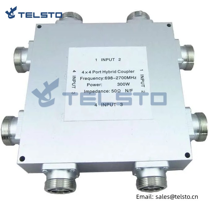
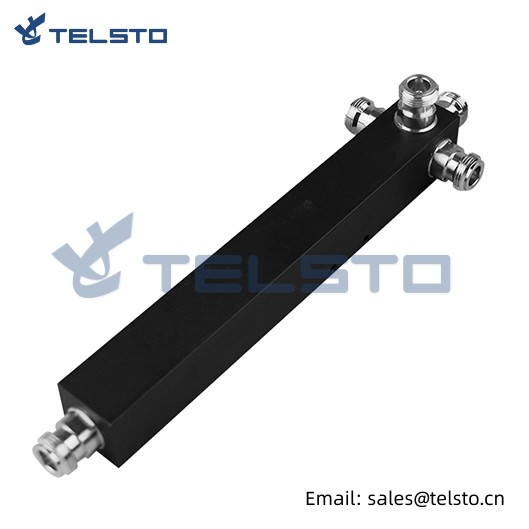
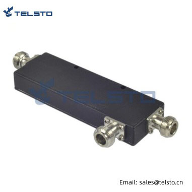
Telsto Power splitters are in 2, 3 and 4 ways
Feature
Telsto Power splitters are in 2, 3 and 4 ways, use stripline and cavity craftwork with silver plated, metal conductors in aluminum housings, with excellent input VSWR, high power ratings, low PIM and very low losses. Excellent design techniques allow bandwidths that extend from 698 to 2700 MHz in housing of convenient length. Cavity splitters are frequently employed in in-building wireless coverage and outdoor distribution systems. because they are virtually indestructible, low loss and low PIM.
Excellent VSWR,
High power rating,
Low PIM,
Multi-Band Frequency Coverage,
Low Cost Design, Design to Cost,
High Reliability and Maintenance free,
Multiple IP Degree Conditions
RoHS Compliant,
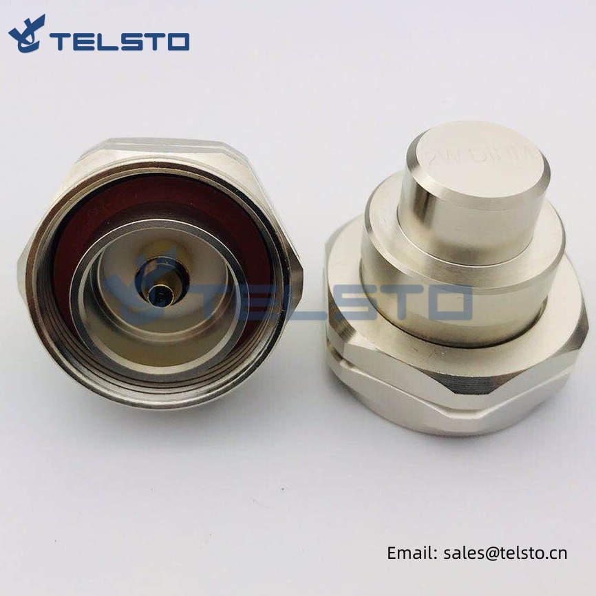
N, DIN 4.3-10 connectors,
Custom Designs Available,
Application
Power splitter allow you to use a common distributor system for all mobile communication applications in the broad frequency range.
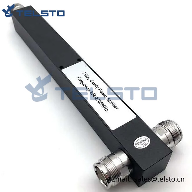
When the signal is distributed for the in-house distribution, in office buildings or sports halls, power splitter can split up the incoming signal in two, three, four or more identical shares.
Divide one signal into multi channel ones, that ensures the system to share common signal source and BTS system.
Meet various demands of network systems with the Ultra-wide band design.
| General Specification | TEL-PS-2 | TEL-PS-3 | TEL-PS-4 |
| Frequency Range (MHz) | 698-2700 | ||
| Way No(dB)* | 2 | 3 | 4 |
| Divided Loss(dB) | 3 | 4.8 | 6 |
| VSWR | ≤1.20 | ≤1.25 | ≤1.30 |
| Insertion Loss(dB) | ≤0.20 | ≤0.30 | ≤0.40 |
| PIM3(dBc) | ≤-150(@+43dBm×2) | ||
| Impedance (Ω) | 50 | ||
| Power Rating(W) | 300 | ||
| Power peak (W) | 1000 | ||
| Connector | N-F | ||
| Temperature Range(℃) | -20~+70 | ||
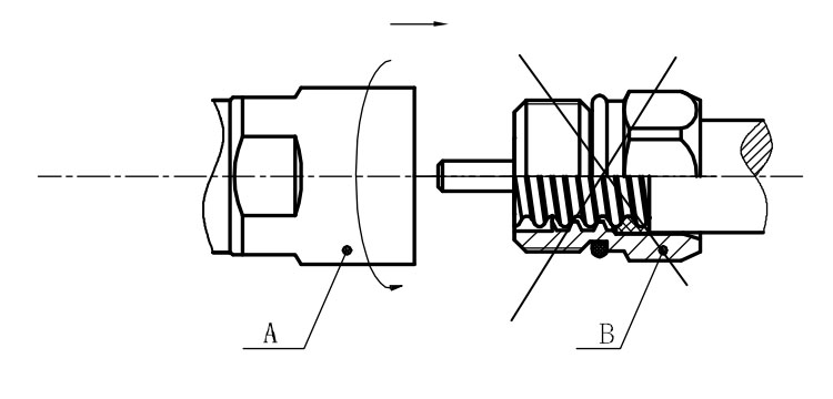
Installation Instructions of N or 7 / 16 or 4310 1 / 2″ super flexible cable
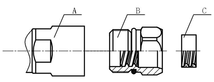
Structure of connector: ( Fig1 )
A. front nut
B. back nut
C. gasket
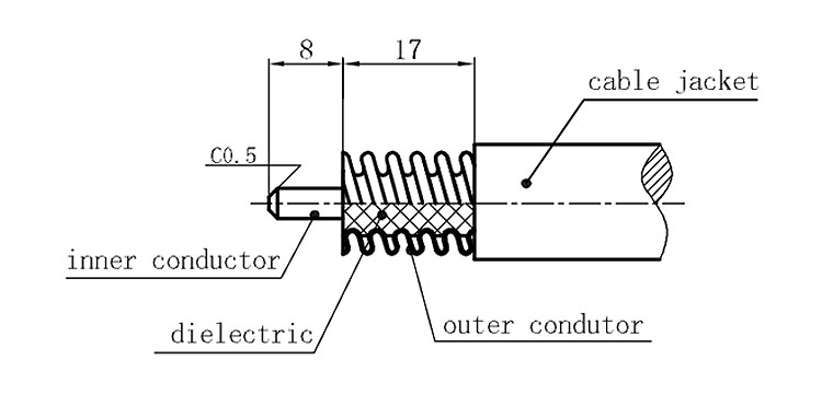
Stripping dimensions is as shown by diagram ( Fig2 ), attention should be paid while stripping:
1. The end surface of inner conductor should be chamfered.
2. Remove impurities such as copper scale and burr on the end surface of the cable.
Assembling the sealing part: Screw the sealing part in along the outer conductor of the cable as shown by the diagram ( Fig3).
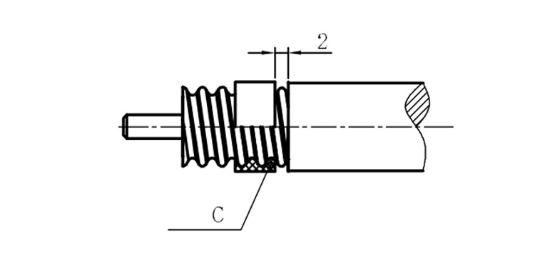
Assembling the back nut (Fig3).
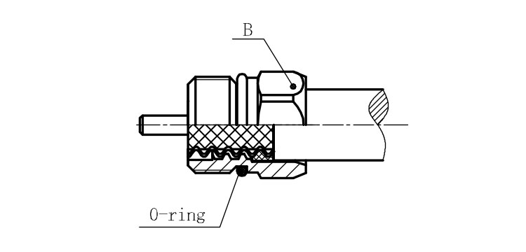
Combine the front and back nut by screwing as shown by diagram ( Figs( 5)
1. Before screwing, smear a layer of lubricating grease on the o-ring.
2. Keep the back nut and the cable motionless, Screw on main shell body on back shell body. Screw down main shell body of back shell body using monkey wrench. Assembling is finished.