Email: sales@telsto.cn
 Telephone: 86-021-6221 2832
 LinkedIn
 Youtube
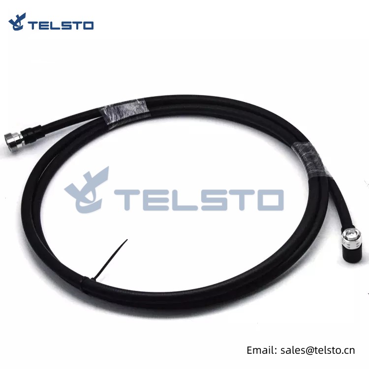


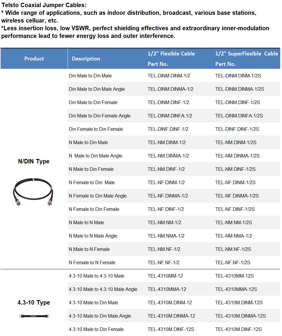
1/2″ super flexible jumper cable DIN 7/16 to DIN 7/16 3M
Applicable for connecting feeder cables with 8TS equipment and antenna, unnecessary of additional waterproof measures, such as waterproof gel or tape, meets waterproof standard IP68.
Standard lengths: 0.5m, 1m, 1.5m, 2m, 3m, customer special requirements on jumper length could be satisfied.
Characteristics & Applications
| Electrical Spec. | |
| Vswr | ≤ 1.15 (800MHz-3GHz) |
| Dielectric withstanding voltage | ≥2500V |
| Dielectric resistance | ≥5000MΩ(500V DC) |
| Pim3 | ≤ -155dBc@2 x 20W |
| Operating temperature | - 55oC ~ + 85oC |
| Insert loss | It depends on leghth of cable |
| Weatherproofing standard | IP68 |
| Cable length | Customized |
| Jacket | Injection molding |
| Connector applicable | N /DIN Type |
Structure and performance parameters
| 1/2" RF Cable | RF Connector | |||
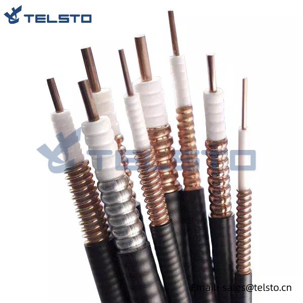
| Material | Inner conductor | Copper clad aluminum wire (Φ4.8mm) | Inner conductor | Brass, tin phosphorus bronze, tinned, thickness≥3μm |
| Dielectric material | Physical foam polyethylene(Φ12.3mm) | Dielectric material | PTFE | |
| Outer conductor | Corrugated copper tube (Φ13.8mm) | Outer conductor | Brass, tri-alloy plated, thickness≥2μm | |
| Jacket | PE/PVC( Φ15.7mm) | Nut | Brass, ni plated, thickness ≥3m | |
| Sealing ring | Silicone rubber | |||
| Electrical and Mechanical Spec. | Characteristic impedance | 50Ω | Characteristic impedance | 50Ω |
| Vswr | ≤ 1.15(DC-3GHz) | Vswr | ≤ 1.15(DC-3GHz) | |
| Standard capacity | 75.8 pF/m | Frequency | DC-3GHz | |
| Velocity | 88% | Dielectric withstanding voltage | ≥4000V | |
| Attenuation | ≥120dB | Contact resistance | Inner conductor ≤ 5.0mΩ Outer conductor≤ 2.5mΩ |
|
| Insulation resistance | ≥5000MΩ | Dielectric resistance | ≥5000MΩ, 500V DC | |
| Peak voltage | 1.6KV | Durability | ≥500 | |
| Peak Power | 40KW | Pims | ≤ -155dBc@2x20W | |
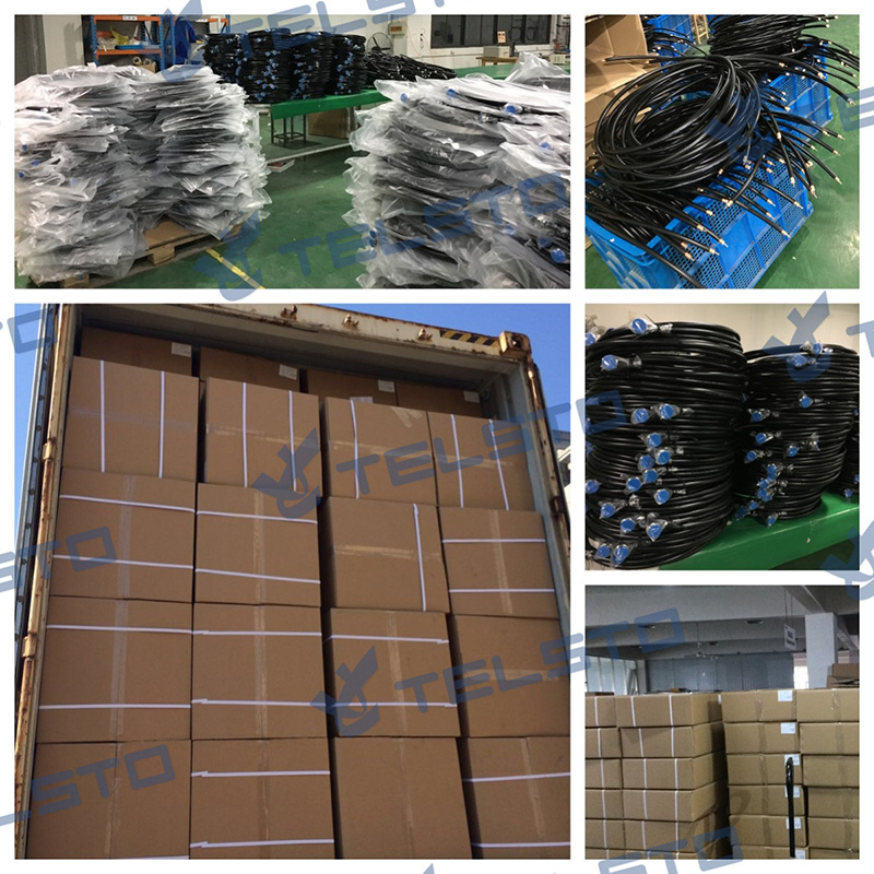
Packing Reference
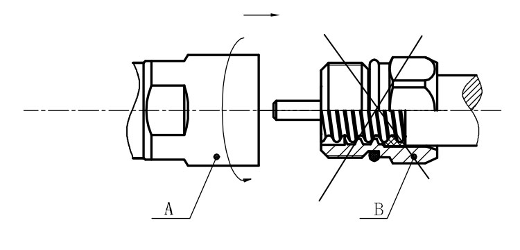
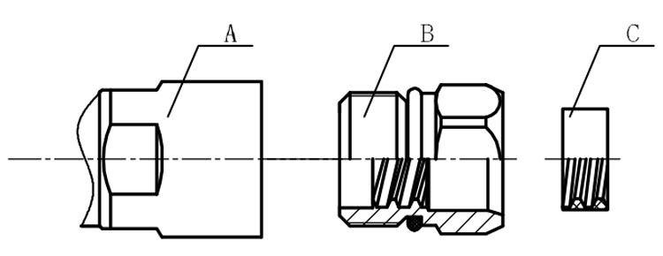
Installation Instructions of N or 7 / 16 or 4310 1 / 2″ super flexible cable
Structure of connector: ( Fig1 )
A. front nut
B. back nut
C. gasket
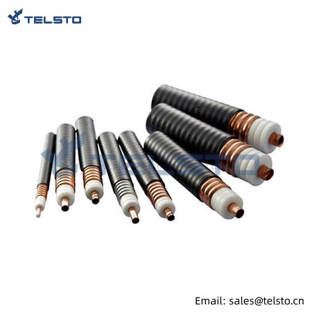
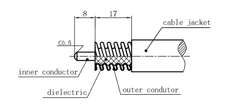
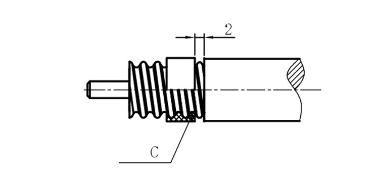
Stripping dimensions is as shown by diagram ( Fig2 ), attention should be paid while stripping:
1. The end surface of inner conductor should be chamfered.
2. Remove impurities such as copper scale and burr on the end surface of the cable.
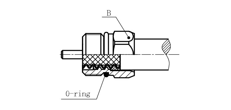
Assembling the sealing part: Screw the sealing part in along the outer conductor of the cable as shown by the diagram ( Fig3).
Assembling the back nut (Fig3).
Combine the front and back nut by screwing as shown by diagram ( Figs( 5)
1. Before screwing, smear a layer of lubricating grease on the o-ring.
2. Keep the back nut and the cable motionless, Screw on main shell body on back shell body. Screw down main shell body of back shell body using monkey wrench. Assembling is finished.