Email: sales@telsto.cn
 Telephone: 86-021-6221 2832
 LinkedIn
 Youtube


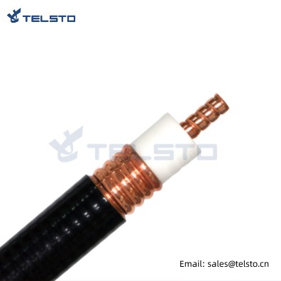
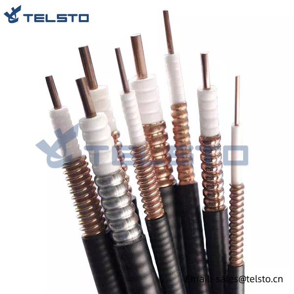
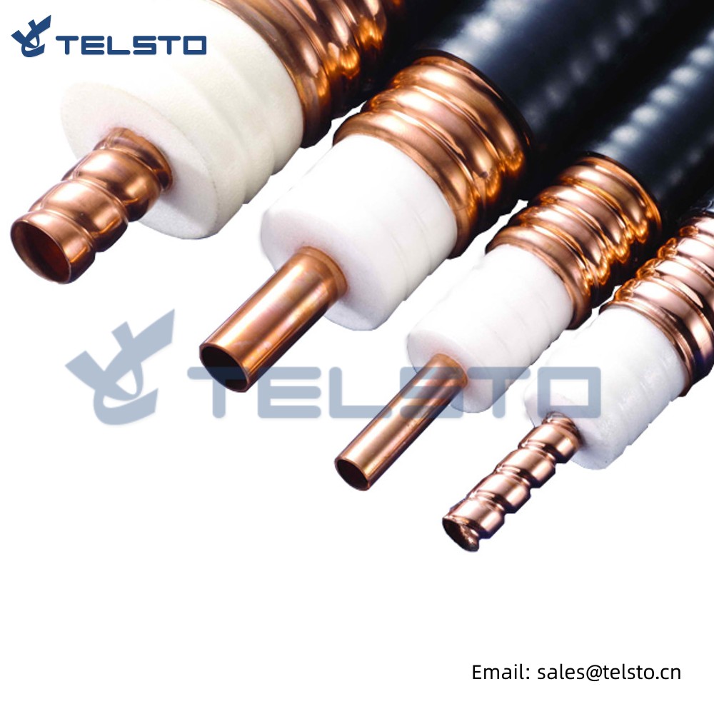
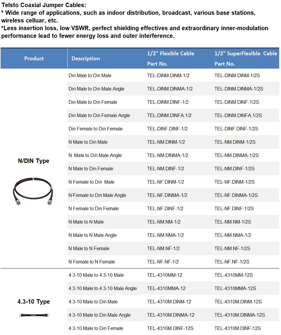
1/2″super flex jumper, 4.3-10 MINI DIN male
| Type name | 4.3-10 mini din male connector | |
| Impedance | 50Ω | |
| Vibration | 100m/S2 (10~500Hz) | |
| Frequency Range | DC-7.5GHz | |
| Insertion Loss | ≤ 0.15dB/6GHz | |
| Withstanding Voltage | 4000V r.m.s at sea level | |
| Working Voltage | 2700Vr.m.s at sea level | |
| Average power | 3Kw max | |
| Insulation Resistance | ≥ 10000 MΩ | |
| Center conductor retention force | ≥ 6N | |
| Durability | ≥ 500(cycles) | |
| Contact resistance | Center Contact ≤ 0.4mΩ | |
| Outer Contact ≤ 1.5mΩ | ||
| Voltage Standing Wave Ratio | Straight | ≤ 1.20/6GHz |
| Right angle | ≤ 1.35/6GHz | |
Our Services
1) Factory sell directly
2) Long-term, strong and steady supplying ability
3) Delivery time: 3-5 working days
4) Package, brand or other designs per your requirements
5) Strong sales promotion policy
6) Ex-factory price and competitive price
7) Good service
8) Replying you asap
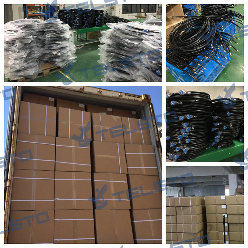
Packing Reference
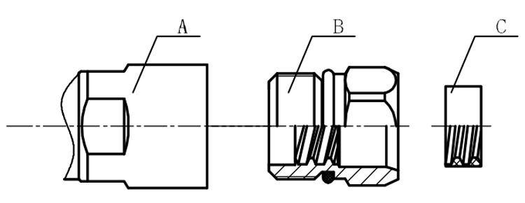
Installation Instructions of N or 7 / 16 or 4310 1 / 2″ super flexible cable
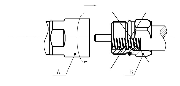
Structure of connector: ( Fig1 )
A. front nut
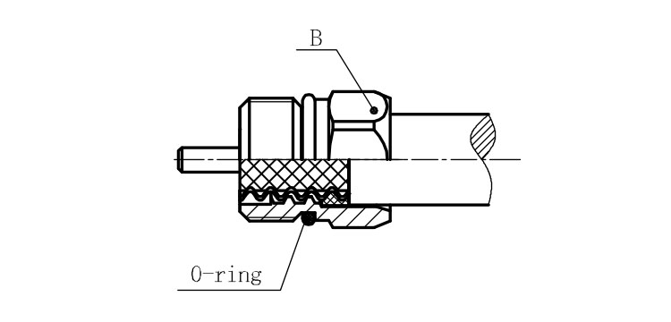
B. back nut
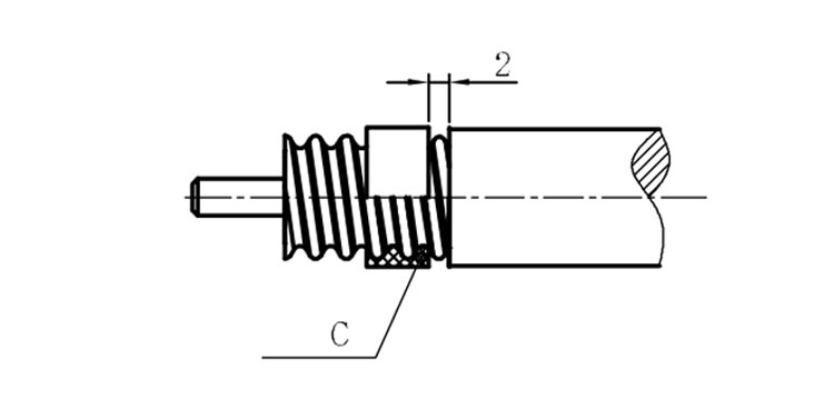
C. gasket
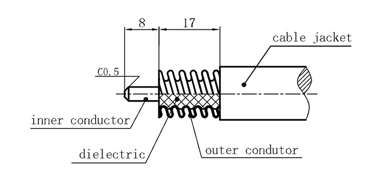
Stripping dimensions is as shown by diagram ( Fig2 ), attention should be paid while stripping:
1. The end surface of inner conductor should be chamfered.
2. Remove impurities such as copper scale and burr on the end surface of the cable.
Assembling the sealing part: Screw the sealing part in along the outer conductor of the cable as shown by the diagram ( Fig3).
Assembling the back nut (Fig3).
Combine the front and back nut by screwing as shown by diagram ( Figs( 5)
1. Before screwing, smear a layer of lubricating grease on the o-ring.
2. Keep the back nut and the cable motionless, Screw on main shell body on back shell body. Screw down main shell body of back shell body using monkey wrench. Assembling is finished.