Email: sales@telsto.cn
 Telephone: 86-021-6221 2832
 LinkedIn
 Youtube
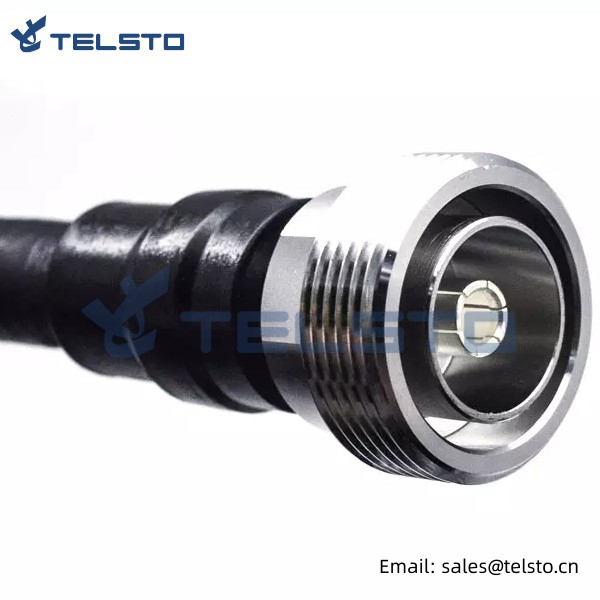

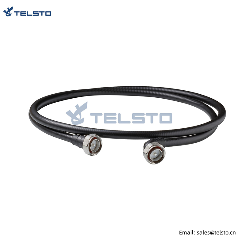
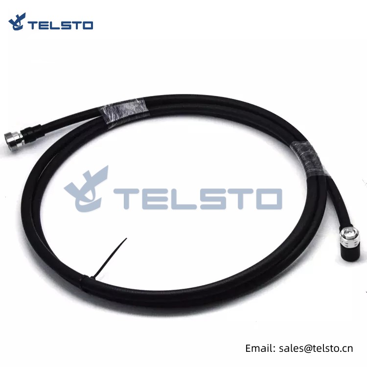
1/2″super flex Jumper cable, DIN 7/16 male to DIN 7/16 male right angle
| Type name | 1/2"s jumper cable din male straight to right angle | |
| Impedance | 50Ω | |
| Vibration | 100m/S2 (10~500Hz) | |
| Frequency Range | DC-6GHz | |
| Insertion Loss | ≤ 0.15dB/6GHz | |
| Withstanding Voltage | 4000V r.m.s at sea level | |
| Working Voltage | 2700Vr.m.s at sea level | |
| Average power | 3Kw max | |
| Insulation Resistance | ≥ 10000 MΩ | |
| Center conductor retention force | ≥ 6N | |
| Durability | ≥ 500(cycles) | |
| Contact resistance | Center Contact ≤ 0.4mΩ | |
| Outer Contact ≤ 1.5mΩ | ||
| Voltage Standing Wave Ratio | Straight | ≤ 1.20/6GHz |
| Right angle | ≤ 1.35/6GHz | |
1. RF coaxial connector
| 1.1 Connector Materials and Plating | |
| Inner conductor | Bronze, plated with silver,plating thickness ≥0.003mm |
| Outer conductor | Brass, plated with ternary alloy,plating thickness≥0.002mm |
| Fastener: Brass | Insulation |
| dielectric | PTFE |
| 1.2 Electrical & Mechanic Feature | |
| Characteristics impedance: | 50Ω |
| Frequency range | DC-3GHz |
| VSWR | ≤1.15 (DC-3GHz) |
| Dielectric strength | ≥2500V |
| Contact resistance | inner conductor≤1.0mΩ, Outer conductor≤0.4mΩ |
| Insulator resistance | ≥5000MΩ (500V DC) |
| VSWR | ≤1.15 (DC-3GHz) |
| PIM(IM3) | ≤-155dBc@2x43dBm |
| Connector durability | ≥500 cycles |
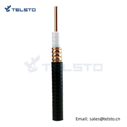
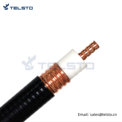
2. RF coaxial cable: 1/2" Super Flexible RF Cable
| 2.1 Materials | |
| Inner conductor | aluminum wire covered with copper (φ3.60mm) |
| Insulation dielectric | polyethylene foam (φ8.90mm) |
| Outer conductor | corrugated copper tube (φ12.20mm) |
| Cable jacket | PE (φ13.60mm) |
| 2.2 Feature | |
| Characteristics impedance | 50Ω |
| Standard capacitor | 80pF/m |
| Transmission rate | 83% |
| Min. single bending radius | 50mm |
| Tensile strength | 700N |
| Insulation resistance | ≥5000MΩ |
| Shielding attenuation | ≥120dB |
| VSWR | ≤1.15 (0.01-3GHz) |
3. Jumper cable
| 3.1 Cable Component Size | |
| Total length of cable assemblies | 1000mm±10, 2000mm±20, 3000mm±25,5000mm±40 |
| 3.2 Electrical feature | |
| Frequency Band | 800-2700MHz |
| Characteristics Impedance | 50Ω±2 |
| Operating Voltage | 1500V |
| VSWR | ≤1.11 (0.8-2.2GHz), ≤1.18 (2.2-2.7GHz) |
| Insulation voltage | ≥2500V |
| Insulation resistance | ≥5000MΩ (500V DC) |
| PIM(IM3) | ≤-155dBc@2x20W |
| 3.3 Environment feature | |
| Waterproof | IP68 |
| Operation temperature range | -40℃ to +85℃ |
| Storage temperature range | -70℃ to +85℃ |
3.4 Insertion Loss:
| Frequency | 1m | 2m | 3m | 5m |
| 890-960MHz | ≤0.15dB | ≤0.26dB | ≤0.36dB | ≤0.54dB |
| 1710-1880MHz | ≤0.20dB | ≤0.36dB | ≤0.52dB | ≤0.80dB |
| 1920-2200MHz | ≤0.26dB | ≤0.42dB | ≤0.58dB | ≤0.92dB |
| 2500-2690MHz | ≤0.30dB | ≤0.50dB | ≤0.70dB | ≤1.02dB |
| 5800-5900MHz | ≤0.32dB | ≤0.64dB | ≤0.96dB | ≤1.6dB |
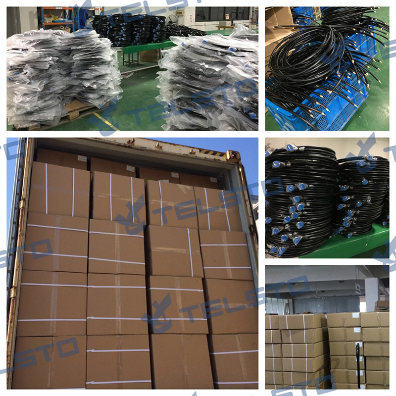
Packing Reference
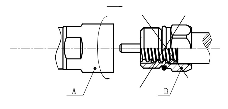
Installation Instructions of N or 7 / 16 or 4310 1 / 2″ super flexible cable
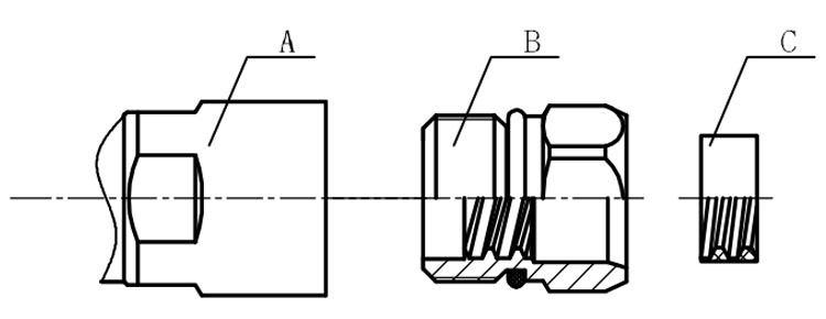
Structure of connector: ( Fig1 )
A. front nut
B. back nut
C. gasket
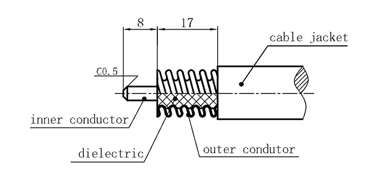
Stripping dimensions is as shown by diagram ( Fig2 ), attention should be paid while stripping:
1. The end surface of inner conductor should be chamfered.
2. Remove impurities such as copper scale and burr on the end surface of the cable.
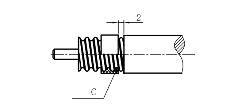
Assembling the sealing part: Screw the sealing part in along the outer conductor of the cable as shown by the diagram ( Fig3).
Assembling the back nut (Fig3).
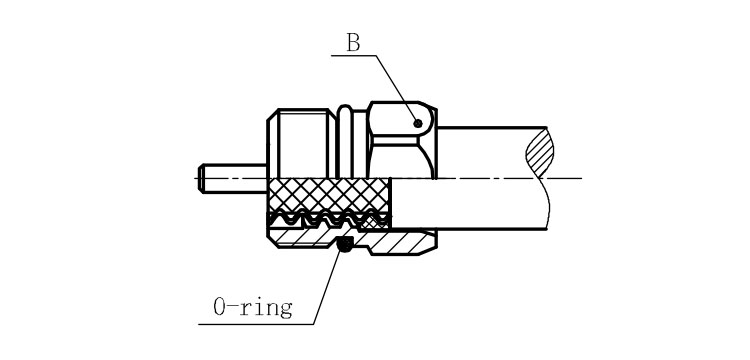
Combine the front and back nut by screwing as shown by diagram ( Figs( 5)
1. Before screwing, smear a layer of lubricating grease on the o-ring.
2. Keep the back nut and the cable motionless, Screw on main shell body on back shell body. Screw down main shell body of back shell body using monkey wrench. Assembling is finished.