Email: sales@telsto.cn
 Telephone: 86-021-6221 2832
 LinkedIn
 Youtube
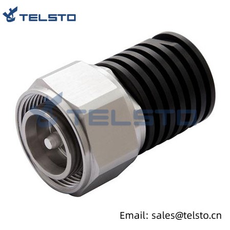
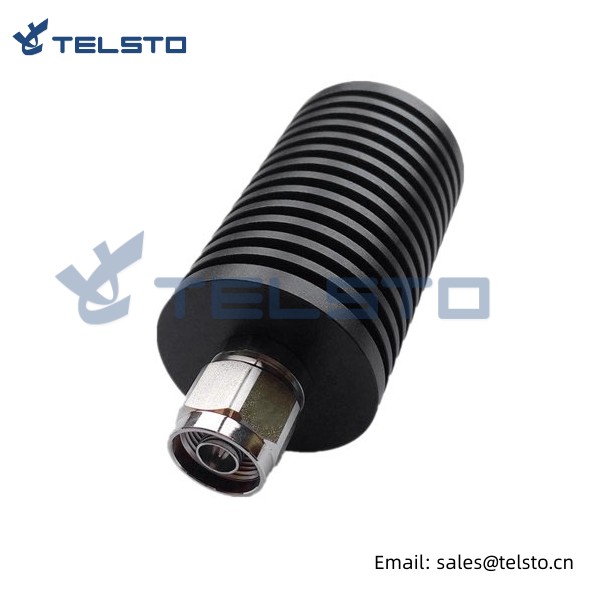
4.3-10 Male Type Load 2W
Termination loads absorb RF & microwave energy and are commonly used as dummy loads of antenna and transmitter. They are also used as match ports in many multi port microwave device such as circular and directional coupler to make these ports which are not involved in the measurement be terminated in their characteristic impedance in order to ensure an accurate measurement.
Termination loads, also call dummy loads, are the passive 1-port interconnect devices, which provide a resistive power termination to properly terminate the output port of a device or to terminate one end of an RF cable. Telsto Termination loads are characterized by low VSWR, high power capacity and performance stability. Widely used for DMA/GMS/DCS/UMTS/WIFI/WIMAX etc.
| Material and Plating | |
| Center contact | Brass / Silver Plating |
| Insulator | PTFE |
| Body & Outer Conductor | Brass / alloy plated with tri-alloy |
| Gasket | Silicon Rubber |
| Electrical Characteristics | |
| Characteristics Impedance | 50 Ohm |
| Frequency Range | DC~6 GHz |
| Working Humidity | 0-90% |
| Insertion Loss | 0.08 @3GHz-6.0GHZ |
| VSWR | 1.1@3GHZ |
| Temperature range ℃ | -35~125 |
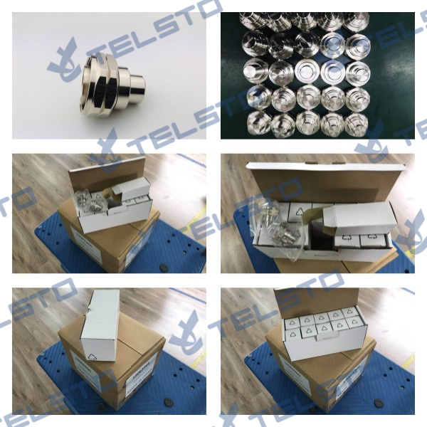
Packing Reference
Installation Instructions of N or 7 / 16 or 4310 1 / 2″ super flexible cable
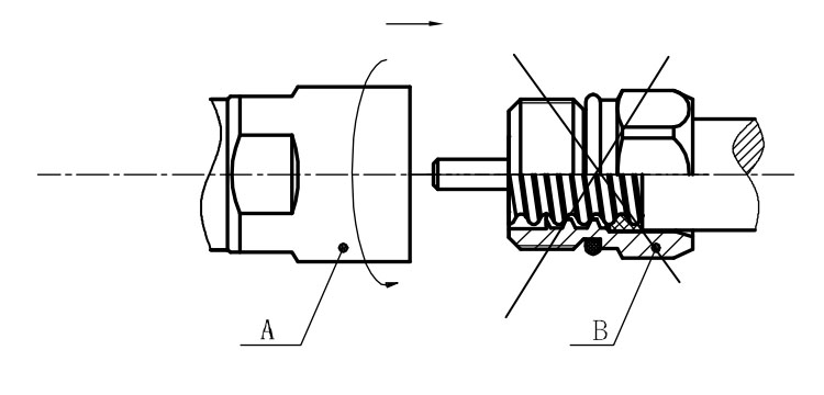
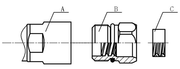
Structure of connector: ( Fig1 )
A. front nut
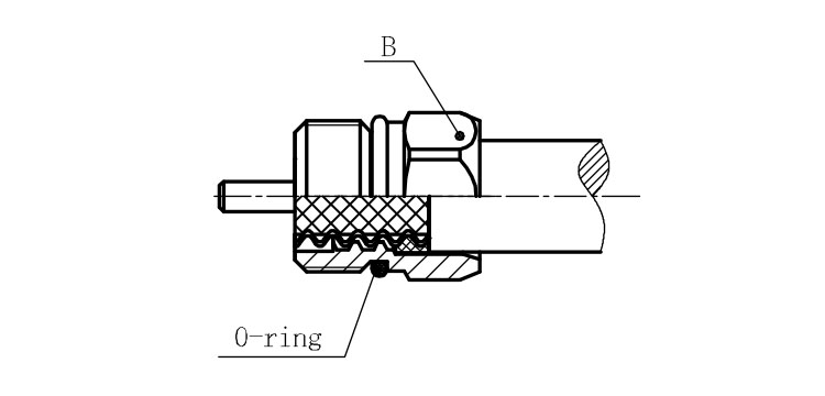
B. back nut
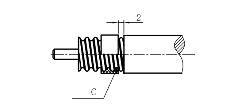
C. gasket
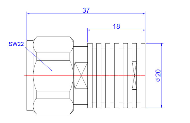
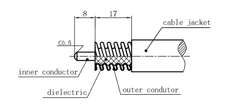
Stripping dimensions is as shown by diagram ( Fig2 ), attention should be paid while stripping:
1. The end surface of inner conductor should be chamfered.
2. Remove impurities such as copper scale and burr on the end surface of the cable.
Assembling the sealing part: Screw the sealing part in along the outer conductor of the cable as shown by the diagram ( Fig3).
Assembling the back nut (Fig3).
Combine the front and back nut by screwing as shown by diagram ( Figs( 5)
1. Before screwing, smear a layer of lubricating grease on the o-ring.
2. Keep the back nut and the cable motionless, Screw on main shell body on back shell body. Screw down main shell body of back shell body using monkey wrench. Assembling is finished.