Email: sales@telsto.cn
 Telephone: 86-021-6221 2832
 LinkedIn
 Youtube
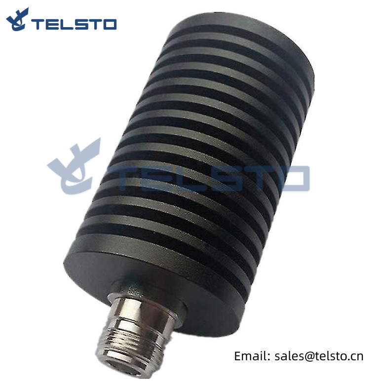
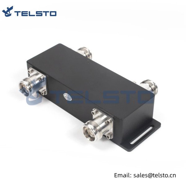
High quality DC-3.0GHz DIN type 100W RF Dummy Load / Termination Load
Termination loads absorb RF & microwave energy and are commonly used as dummy loads of antenna and transmitter. They are also used as match ports in many multi port microwave device such as circulation and directional couple to make these ports which are not involved in the measurement be terminated in their characteristic impedance in order to ensure an accurate measurement.
Termination loads, also call dummy loads, are the passive 1-port interconnect devices, which provide a resistive power termination to properly terminate the output port of a device or to terminate one end of an RF cable. Telsto Termination loads are characterized by low VSWR, high power capacity and performance stability. Widely used for DMA/GMS/DCS/UMTS/WIFI/WIMAX etc.
Technical Specifications:
| Product | Description | Part No. |
| Termination Load | N Male / N Female, 2W | TEL-TL-NM/F2W |
| N Male / N Female, 5W | TEL-TL-NM/F5W | |
| N Male / N Female, 10W | TEL-TL-NM/F10W | |
| N Male / N Female, 25W | TEL-TL-NM/F25W | |
| N Male / N Female, 50W | TEL-TL-NM/F50W | |
| N Male / N Female, 100W | TEL-TL-NM/F100W | |
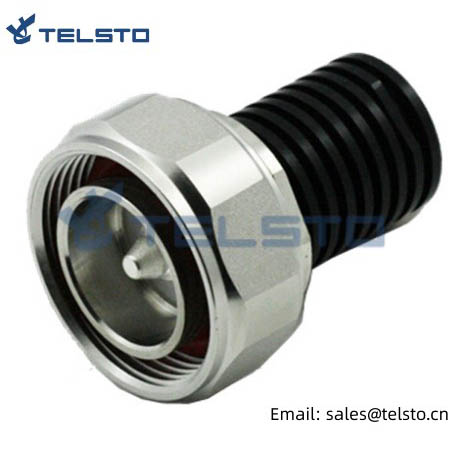
| DIN Male / Female, 10W | TEL-TL-DINM/F10W | |
| DIN Male / Female, 25W | TEL-TL-DINM/F25W | |
| DIN Male / Female, 50W | TEL-TL-DINM/F50W | |
| DIN Male / Female, 100W | TEL-TL-DINM/F100W |
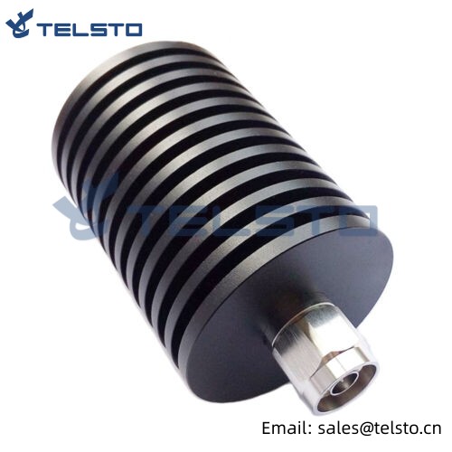
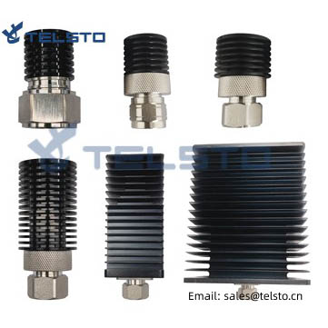
100W Coaxial Fixed Termination Load is one of Telsto RF Load Products Line. Telsto is capable of.
manufacturing and providing 1W, 2W, 5W, 10W, 15W, 20W, 25W, 30W, 50W, 100W, 200W, 300W, 500W RF.
Dummy Load. The Frequency can reach DC-3G, DC-6G, DC-8G, DC-12.4G ,DC-18G, DC-26G, DC-40G. RF Connectors can be N-type, SMA-type, DIN-type, TNC-type and BNC-type.
Our service
1. Professional skills support.
2. OEM services is available.
3. Within 24 hours reply.
4. We will try our best to provide support whatever you need and we can do.
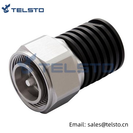
The series of Termination Loads is medium power loads which operate from DC to 3GHz. Cooling fins minimize temperature rise of the resistive film terminating element, contained within a carefully matched housing. Standard connectors are N and 7 /16 DIN, male and female.
Features
● Multi-band version for DC-3GHz
● High reliability
● Low VSWR
● Ideal for BST applications
● N & 7 /16 DIN male/female connectors
| Part No. | Frequency Range (MHz) | lmpedance(O) | Power Rating(W) | VSWR | Temperature Range(°C) |
| TEL-TL-NM/F2W | DC-3GHz | 50 | 2 | 1.15: 1 | -10-50 |
| TEL-TL-NM/F5W | DC-3GHz | 50 | 5 | 1.15: 1 | -10-50 |
| TEL-TL-NM/F10W | DC-3GHz | 50 | 10 | 1.15: 1 | -10-50 |
| TEL-TL-NM/F25W | DC-3GHz | 50 | 25 | 1.15: 1 | -10-50 |
| TEL-TL-NM/F50W | DC-3GHz | 50 | 50 | 1.15: 1 | -10-50 |
| TEL-TL-NM/F100W | DC-3GHz | 50 | 100 | 1.25: 1 | -10-50 |
| TEL-TL-DINM/F10W | DC-3GHz | 50 | 10 | 1.15: 1 | -10-50 |
| TEL-TL-DINM/F25W | DC-3GHz | 50 | 25 | 1.15: 1 | -10-50 |
| TEL-TL-DINM/F50W | DC-3GHz | 50 | 50 | 1.15: 1 | -10-50 |
| TEL-TL-DINM/F100W | DC-3GHz | 50 | 100 | 1.25: 1 | -10-50 |
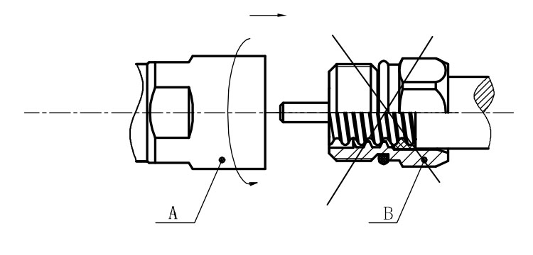
Installation Instructions of N or 7 / 16 or 4310 1 / 2″ super flexible cable
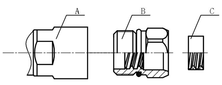
Structure of connector: ( Fig1 )
A. front nut
B. back nut
C. gasket
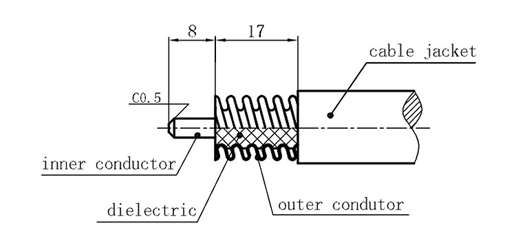
Stripping dimensions is as shown by diagram ( Fig2 ), attention should be paid while stripping:
1. The end surface of inner conductor should be chamfered.
2. Remove impurities such as copper scale and burr on the end surface of the cable.
Assembling the sealing part: Screw the sealing part in along the outer conductor of the cable as shown by the diagram ( Fig3).
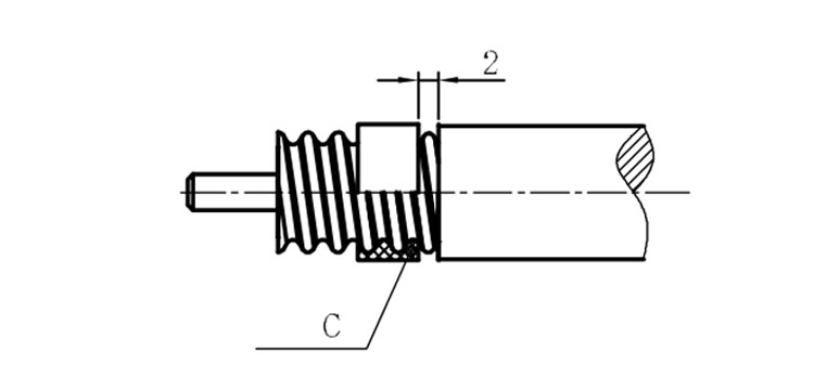
Assembling the back nut (Fig3).
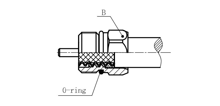
Combine the front and back nut by screwing as shown by diagram ( Figs( 5)
1. Before screwing, smear a layer of lubricating grease on the o-ring.
2. Keep the back nut and the cable motionless, Screw on main shell body on back shell body. Screw down main shell body of back shell body using monkey wrench. Assembling is finished.