Email: sales@telsto.cn
 Telephone: 86-021-6221 2832
 LinkedIn
 Youtube

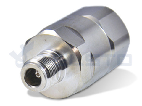
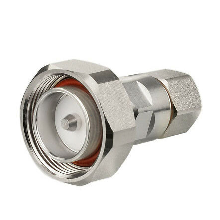
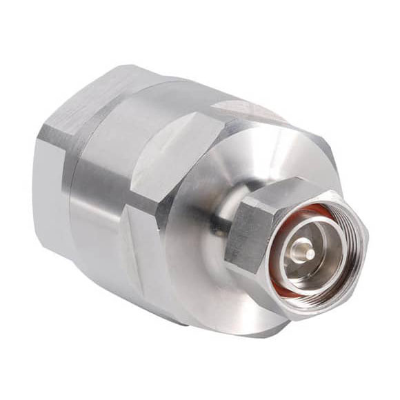
N Female to 7/8” coaxial cable connector
N series coaxial connectors are medium-sized, threaded coupling connectors designed for use from DC to 11 GHz. Their consistently low broadband VSWR have made them popular over the years in many applications. The N series connector is impedance matched to 50 ohm cables. Cable terminations are available in crimp, clamp and solder configurations. The threaded coupling ensures proper mating in applications where shock and extreme vibration are design considerations. N connectors are used in aerospace, broadcast audio and video applications as well as many microwave components such as filters, couples, dividers, amplifiers and attenuator to name a few.
1. We focus on RF Connector & RF Adapter &Cable Assembly &Antenna.
2. We have a vigorous and creative R&D team with the fullest mastery of the core technology.
We commit ourselves to the development of high performance connector production, and dedicate ourselves to achieving a leading position in connector innovation and production.
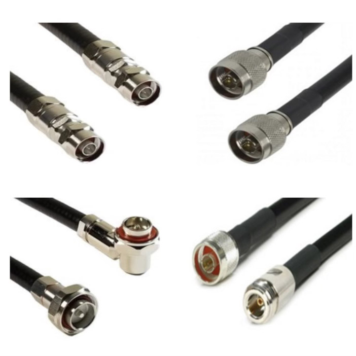
3. Our custom RF cable assemblies are built-in and shipped worldwide.
4. RF cable assemblies can be produced with many different connector types and custom lengths depending on your needs and applications.
Related
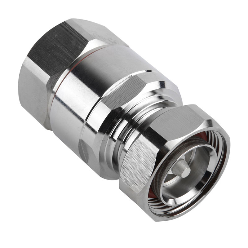
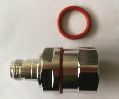
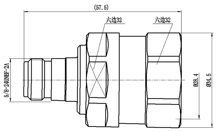
Model: TEL-NF.78-RFC
Description:
N Female connector for 7/8″ Flexible cable
| Material and Plating | |
| Center contact | Brass / Silver Plating |
| Insulator | PTFE |
| Body & Outer Conductor | Brass / alloy plated with tri-alloy |
| Gasket | Silicon Rubber |
| Electrical Characteristics | |
| Characteristics Impedance | 50 Ohm |
| Frequency Range | DC~3 GHz |
| Insulation Resistance | ≥5000MΩ |
| Dielectric Strength | ≥2500 V rms |
| Center contact resistance | ≤1.0 mΩ |
| Outer contact resistance | ≤0.25 mΩ |
| Insertion Loss | ≤0.1dB@3GHz |
| VSWR | ≤1.15@3.0GHz |
| Temperature range | -40~85℃ |
| PIM dBc(2×20W) | ≤-160 dBc(2×20W) |
| Waterproof | IP67 |
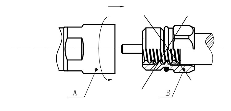
Installation Instructions of N or 7 / 16 or 4310 1 / 2″ super flexible cable
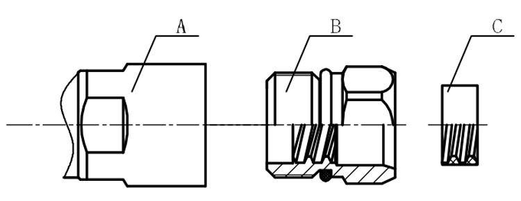
Structure of connector: ( Fig1 )
A. front nut
B. back nut
C. gasket
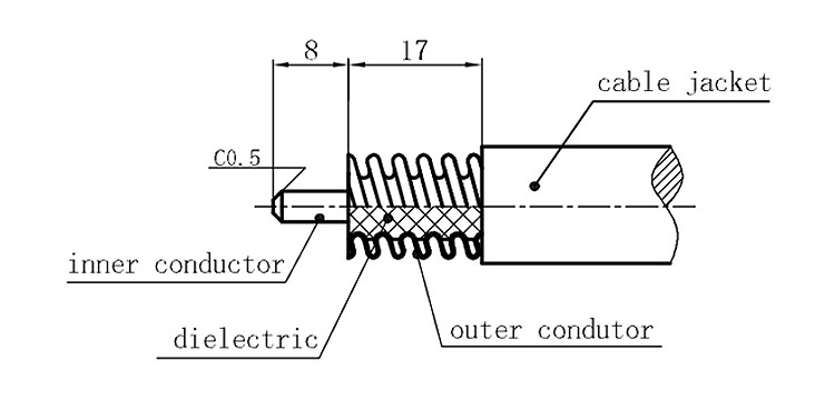
Stripping dimensions is as shown by diagram ( Fig2 ), attention should be paid while stripping:
1. The end surface of inner conductor should be chamfered.
2. Remove impurities such as copper scale and burr on the end surface of the cable.
Assembling the sealing part: Screw the sealing part in along the outer conductor of the cable as shown by the diagram ( Fig3).
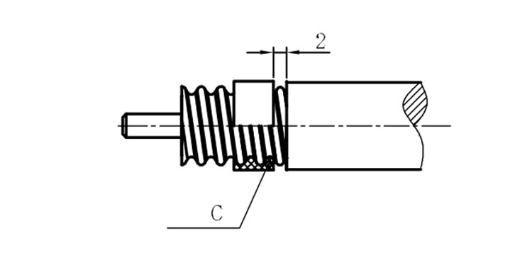
Assembling the back nut (Fig3).
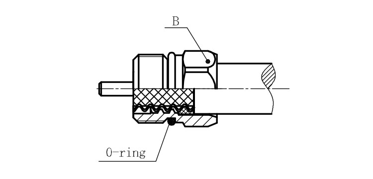
Combine the front and back nut by screwing as shown by diagram ( Figs( 5)
1. Before screwing, smear a layer of lubricating grease on the o-ring.
2. Keep the back nut and the cable motionless, Screw on main shell body on back shell body. Screw down main shell body of back shell body using monkey wrench. Assembling is finished.