Email: sales@telsto.cn
 Telephone: 86-021-6221 2832
 LinkedIn
 Youtube
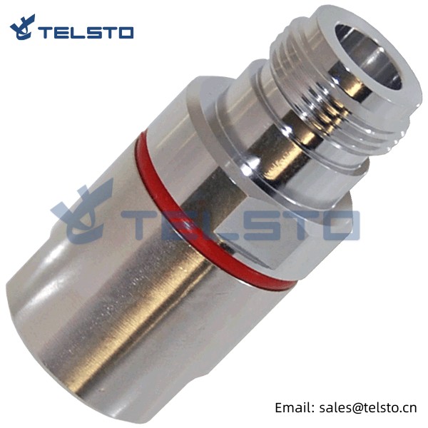
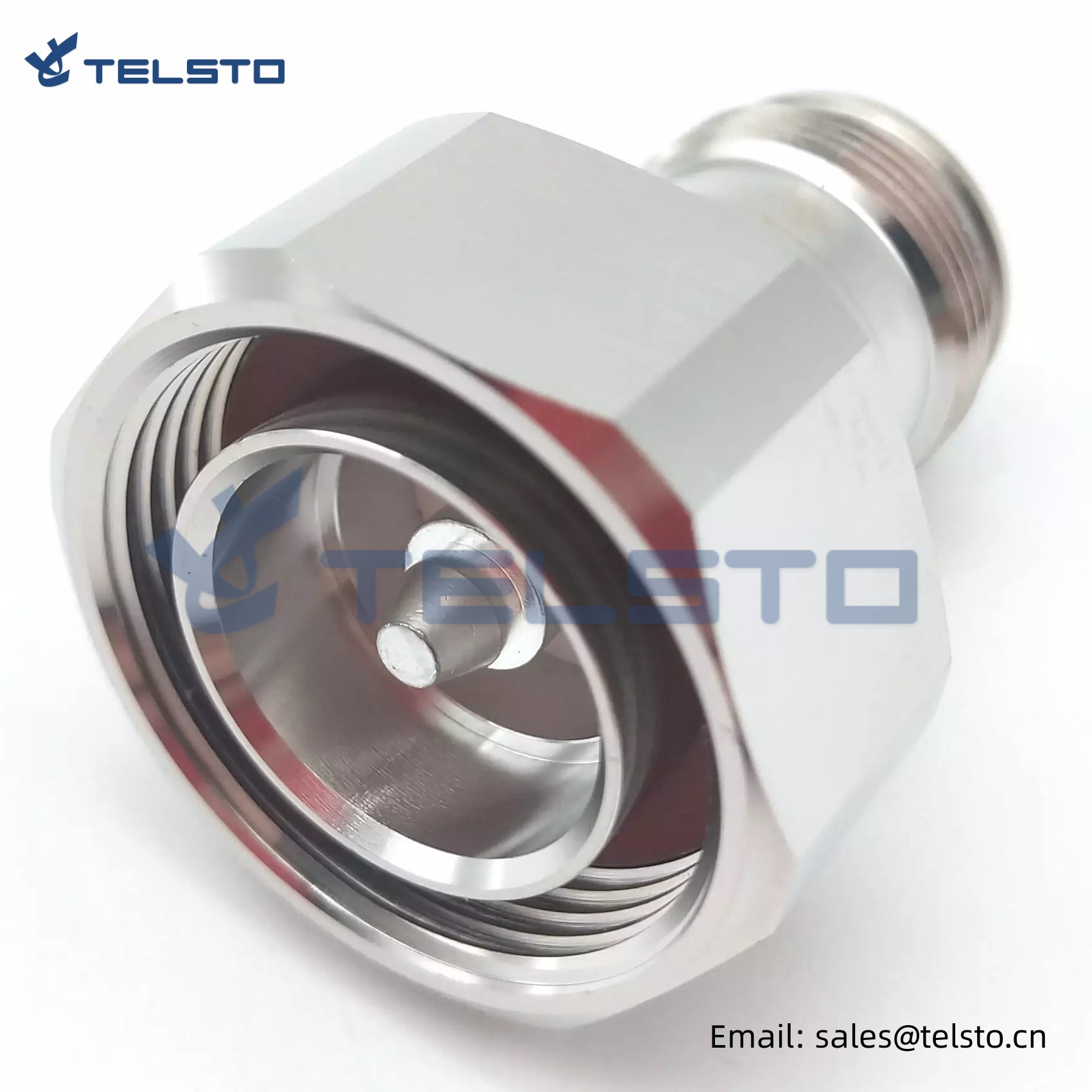
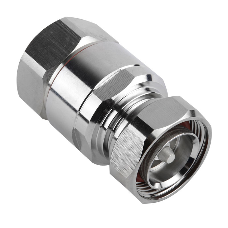
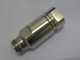
N Female connector for 1/2″ flexible RF cable
N Connector is a threaded RF Connector used for linking with coaxial cable. It has both 50 Ohm and standard 75 Ohm impedance. N Connectors Applications Antennas, Base Stations, Broadcast, WLAN, Cable Assemblies, Cellular, Components test & Instrumentation equipment, Microwave Radio, MIL-Afro PCS, Radar, Radio equipment, Satcom, Surge Protection.
With the exception of the inner contacts, the interface dimensions of the 75 ohm connector have been traditionally identical to that of the 50 ohm connector. It has thus been possible unintentionally to cross couple connectors with the following effects:
(A) 75 ohm male pin - 50 ohm female pin: open circuit inner contact.
(B) 50 ohm male pin - 75 ohm female pin: mechanical destruction of 75 ohm inner socket contact.
Note: These characteristics are typical and may not apply to all connectors.
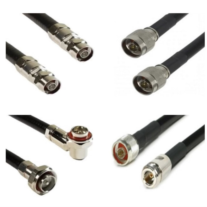
Applications
• Cable Assembly
• Antenna
• WLAN
• Radio
• GPS
• Base Station
• Afro
• Radar
• PCS
• Surge Protection
• Telecom
• Instrumentation
• Broadcast
• Satcom
• Instrumentation
Related
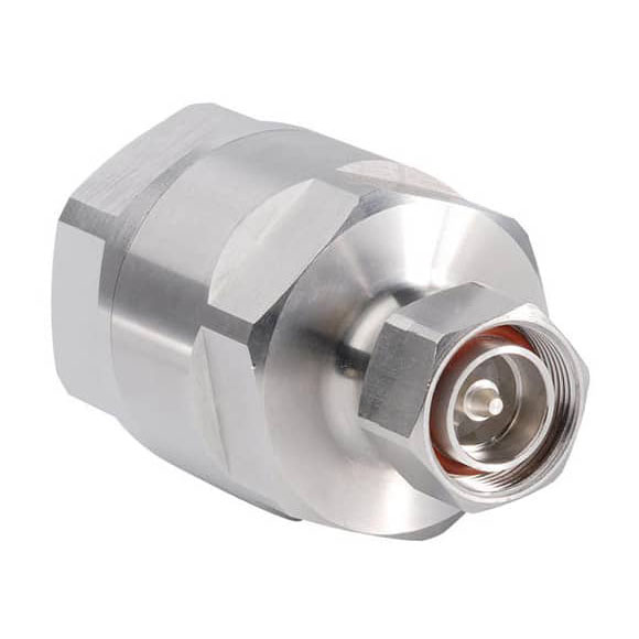
Model: TEL-NF.12-RFC
Description
N Female connector for 1/2″ flexible cable
| Material and Plating | |
| Center contact | Brass / Silver Plating |
| Insulator | PTFE |
| Body & Outer Conductor | Brass / alloy plated with tri-alloy |
| Gasket | Silicon Rubber |
| Electrical Characteristics | |
| Characteristics Impedance | 50 Ohm |
| Frequency Range | DC~3 GHz |
| Insulation Resistance | ≥5000MΩ |
| Dielectric Strength | ≥2500 V rms |
| Center contact resistance | ≤1.0 mΩ |
| Outer contact resistance | ≤1.0 mΩ |
| Insertion Loss | ≤0.05dB@3GHz |
| VSWR | ≤1.08@-3.0GHz |
| Temperature range | -40~85℃ |
| PIM dBc(2×20W) | ≤-160 dBc(2×20W) |
| Waterproof | IP67 |
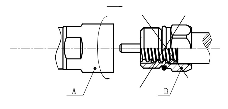
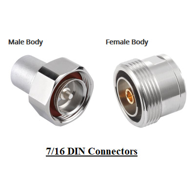
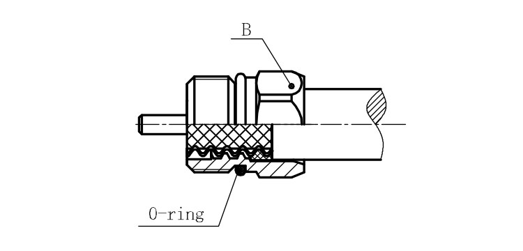
Installation Instructions of N or 7 / 16 or 4310 1 / 2″ super flexible cable
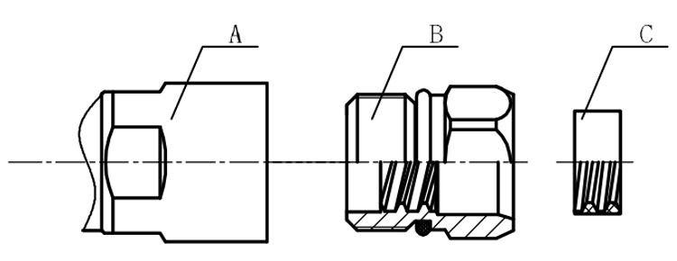
Structure of connector: ( Fig1 )
A. front nut
B. back nut
C. gasket
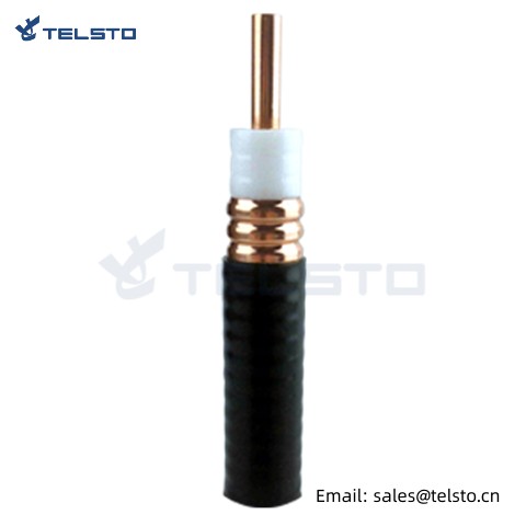
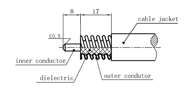
Stripping dimensions is as shown by diagram ( Fig2 ), attention should be paid while stripping:
1. The end surface of inner conductor should be chamfered.
2. Remove impurities such as copper scale and burr on the end surface of the cable.
Assembling the sealing part: Screw the sealing part in along the outer conductor of the cable as shown by the diagram ( Fig3).
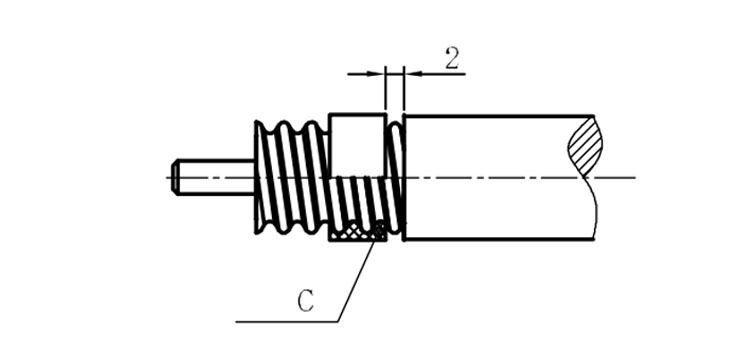
Assembling the back nut (Fig3).
Combine the front and back nut by screwing as shown by diagram ( Figs( 5)
1. Before screwing, smear a layer of lubricating grease on the o-ring.
2. Keep the back nut and the cable motionless, Screw on main shell body on back shell body. Screw down main shell body of back shell body using monkey wrench. Assembling is finished.