Email: sales@telsto.cn
 Telephone: 86-021-6221 2832
 LinkedIn
 Youtube
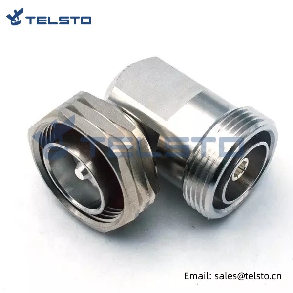
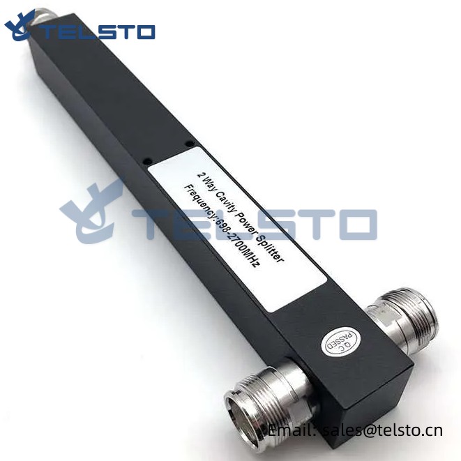
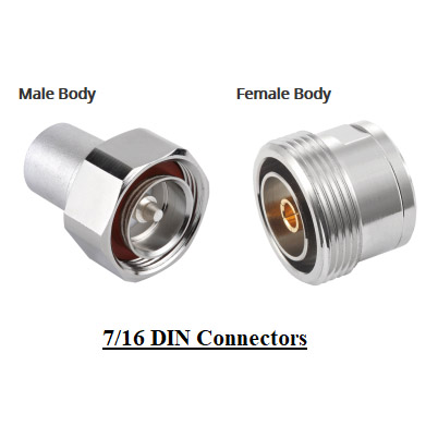
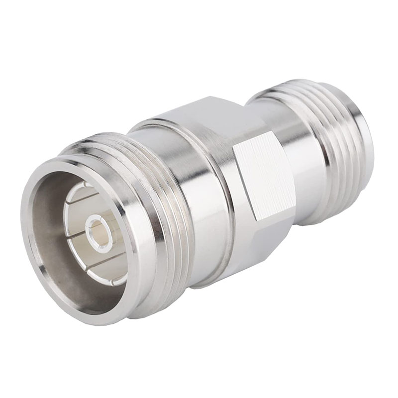
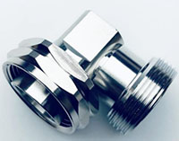
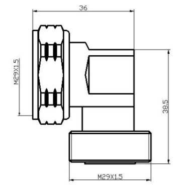
RF coaxial adapter 7/16 DIN female to DIN male right angle
Features and Benefits
50 Ohm nominal impedance
Ideal for applications requiring low PIM and low attenuation
IP-67 compliant
Applications
Distributed Antenna Systems (DAS)
Base Stations
Wireless Infrastructure
Related
Model: TEL-DINF.DINMA-AT
Description:
DIN Female to Din Male Right Angle RF Adapter
| Material and Plating | ||
| Material | Plating | |
| Body | Brass | Tri-Alloy |
| Insulator | PTFE | / |
| Center conductor | Phosphor bronze | Ag |
| Electrical Characteristics | |
| Characteristics Impedance | 50 Ohm |
| Port 1 | 7/16 DIN Male |
| Port 2 | 7/16 DIN Female |
| Type | Right Angle |
| Frequency Range | DC-7.5GHz |
| VSWR | ≤1.10(3.0G) |
| PIM | ≤-160dBc |
| Dielectric Withstanding Voltage | ≥4000V RMS,50Hz,at sea level |
| Dielectric Resistance | ≥10000MΩ |
| Contact Resistance | Center Contact ≤0.40mΩOuter Contact ≤0.25mΩ |
| Mechanical | |
| Durability | Mating cycles ≥500 |
| Environmental | |
| Temperature range | -40~+85℃ |
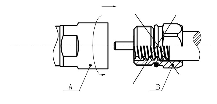
Installation Instructions of N or 7 / 16 or 4310 1 / 2″ super flexible cable
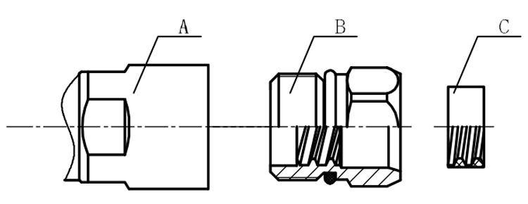
Structure of connector: ( Fig1 )
A. front nut
B. back nut
C. gasket
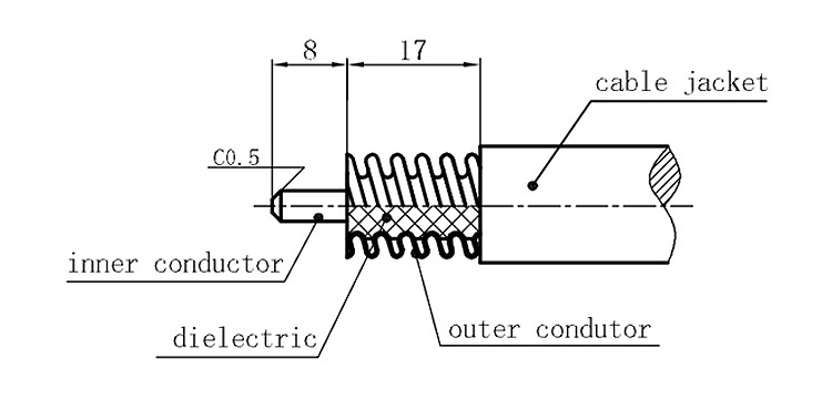
Stripping dimensions is as shown by diagram ( Fig2 ), attention should be paid while stripping:
1. The end surface of inner conductor should be chamfered.
2. Remove impurities such as copper scale and burr on the end surface of the cable.
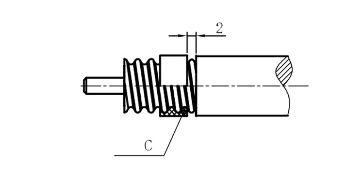
Assembling the sealing part: Screw the sealing part in along the outer conductor of the cable as shown by the diagram ( Fig3).
Assembling the back nut (Fig3).
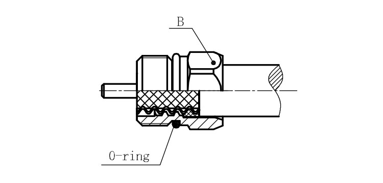
Combine the front and back nut by screwing as shown by diagram ( Figs( 5)
1. Before screwing, smear a layer of lubricating grease on the o-ring.
2. Keep the back nut and the cable motionless, Screw on main shell body on back shell body. Screw down main shell body of back shell body using monkey wrench. Assembling is finished.