Email: sales@telsto.cn
 Telephone: 86-021-6221 2832
 LinkedIn
 Youtube
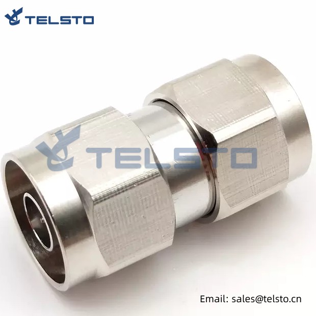
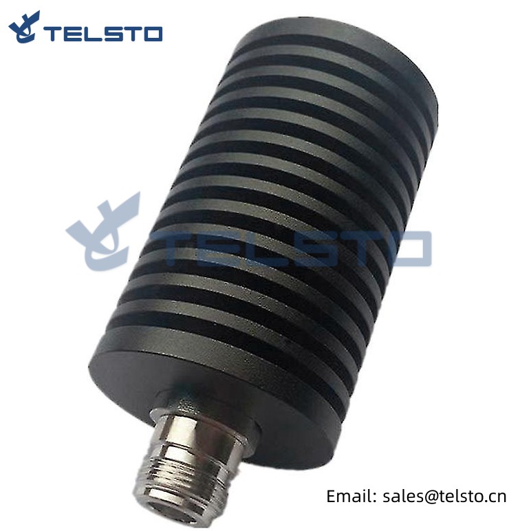
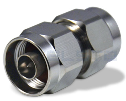
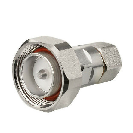
RF Coaxial N Male to N Male Adapter Connector
Telsto RF connector is a connector widely used in the field of wireless communication. Its operating frequency range is DC-3 GHz. It has excellent VSWR performance and low passive intermodulation. It has very stable signal transmission and excellent communication quality. Therefore, this connector is very suitable for cellular base stations, distributed antenna systems (DAS) and cell applications to ensure high-speed and efficient communication and data transmission.
At the same time, the coaxial adapter is also an essential connection tool. It can quickly change the connector type and gender to meet the needs of different devices and connection methods, while ensuring the firmness and stability of the connection. No matter in the laboratory, production line or practical application, coaxial adapter is one of the necessary tools. It can greatly simplify the connection process, improve work efficiency, reduce the possibility of misoperation and connection errors, and ensure the quality and safety of equipment connection.
In short, Telsto RF connectors and coaxial adapters are indispensable tools in the field of wireless communication. Their excellent performance and stability can ensure the efficiency, speed and stability of wireless communication. For professionals engaged in the field of wireless communication, it is very important to master the use methods and skills of these tools, which can help them better complete various communication tasks and achieve better results in their daily work
| Electrical Specifications | |
| Impedance | 50 Ω |
| Frequency | DC-3GHz / Customized |
| VSWR | 1.15 Max |
| Proof Voltage | 2500V |
| Working Voltage | 1400V |
| Connector A | N male |
| Connector B | N male |
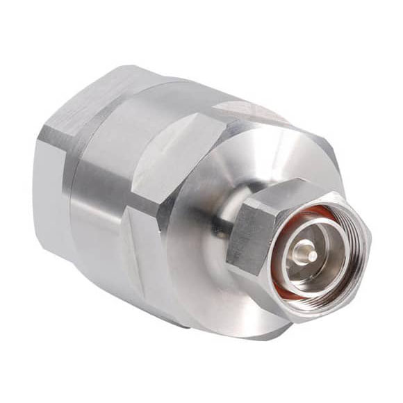
Adapter: N Male to N Male
● Allows interconnection of devices with N female interfaces.
● Use for Coaxial extension, coaxial interface conversion, coax retrofit applications.
● RoHS compliant.
4.3-10 types for your choices
| Product | Description | Part No. |
| RF Adapter | 4.3-10 Female to Din Female Adapter | TEL-4310F.DINF-AT |
| 4.3-10 Female to Din Male Adapter | TEL-4310F.DINM-AT | |
| 4.3-10 Male to Din Female Adapter | TEL-4310M.DINF-AT | |
| 4.3-10 Male to Din Male Adapter | TEL-4310M.DINM-AT |
Related
Model: TEL-NM.NM-AT
Description
N Male to N Male RF Adapter
| Material and Plating | |
| Center contact | Brass / Silver Plating |
| Insulator | PTFE |
| Body & Outer Conductor | Brass / alloy plated with tri-alloy |
| Gasket | Silicon Rubber |
| Electrical Characteristics | |
| Characteristics Impedance | 50 Ohm |
| Frequency Range | DC~3 GHz |
| Insulation Resistance | ≥5000MΩ |
| Dielectric Strength | ≥2500 V rms |
| Center contact resistance | ≤1.0 mΩ |
| Outer contact resistance | ≤0.25 mΩ |
| Insertion Loss | ≤0.15dB@3GHz |
| VSWR | ≤1.1@-3.0GHz |
| Temperature range | -40~85℃ |
| PIM dBc(2×20W) | ≤-160 dBc(2×20W) |
| Waterproof | IP67 |
Installation Instructions of N or 7 / 16 or 4310 1 / 2″ super flexible cable
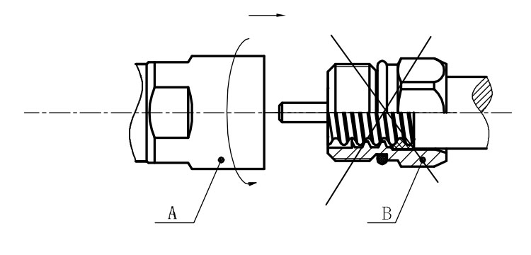
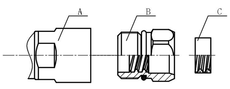
Structure of connector: ( Fig1 )
A. front nut
B. back nut
C. gasket
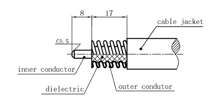
Stripping dimensions is as shown by diagram ( Fig2 ), attention should be paid while stripping:
1. The end surface of inner conductor should be chamfered.
2. Remove impurities such as copper scale and burr on the end surface of the cable.
Assembling the sealing part: Screw the sealing part in along the outer conductor of the cable as shown by the diagram ( Fig3).
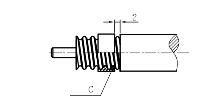
Assembling the back nut (Fig3).
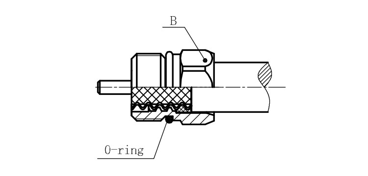
Combine the front and back nut by screwing as shown by diagram ( Figs( 5)
1. Before screwing, smear a layer of lubricating grease on the o-ring.
2. Keep the back nut and the cable motionless, Screw on main shell body on back shell body. Screw down main shell body of back shell body using monkey wrench. Assembling is finished.