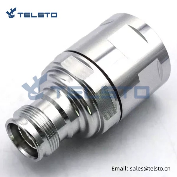
4.3-10 female Straight RF Connector for 7/8″ Feeder cable Screw Type
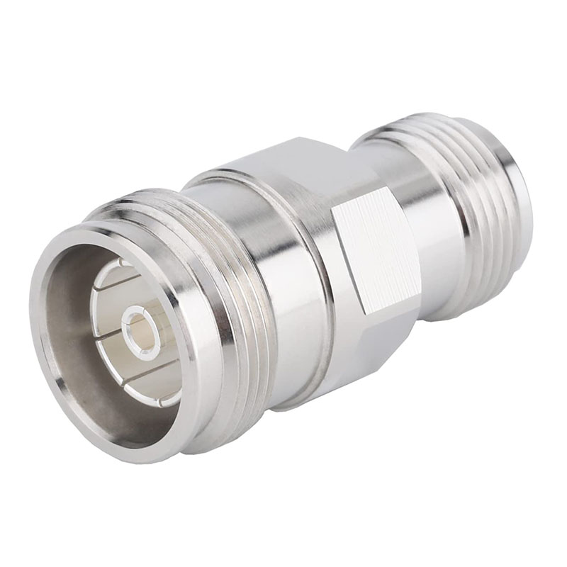
1. The 4.3-10 connector system is designed to meet the latest requirements of mobile network equipment to connect the RRU to the antenna.
2. The 4.3-10 connector system is better than 7/16 connectors in terms of size, robustness, performance, and other parameters, separate electrical and mechanical components yield very stable PIM performance, which results in a lower coupling torque. These series of connectors are compact sizes, best electrical performance, low PIM and coupling torque as Well as easy installation, these designs provide excellent VSWR performance up to 6.0 GHz.
Features
1. 100% PIM tested
2. Ideal for applications requiring low PIM and low attenuation
3. 50 Ohm nominal impedance
4. IP-68 compliant in the unrated condition
5. Frequency range DC to 6GHz
Applications
1. Distributed Antenna System (DAS)
2. Base Stations
3. Wireless Infrastructure
4. Telecom
5. Filters and Combiners
1.4.3-10 Connector system, which is the latest product specially designed to connect mobile network equipment and antenna.
With the rapid development of mobile communication technology, more and more users need high-speed and reliable network connection. To meet these requirements, our 1.4.3-10 connector system came into being. This system is based on the latest industry standards and aims to provide high-quality connection services for mobile network devices, connecting RRUs to antennas. The connector system uses high-quality materials to ensure its stability and durability. At the same time, its design takes into account various use scenarios and environmental conditions, so as to ensure its normal operation under various weather and climatic conditions. This means that our connector system can ensure the reliability of data transmission even under severe weather conditions. In addition, our 1.4.3-10 connector system also has the advantages of easy installation and maintenance. This allows it to be installed quickly and reduces the cost of installation and maintenance. Moreover, our connector system adopts standardized interfaces, which means it can be compatible with other devices, making it more flexible and extensible. In short, our 1.4.3-10 connector system is a high-quality, stable, durable, easy to install and maintain, flexible and scalable connector system, which is designed to meet the latest requirements of mobile network equipment to connect RRU to antenna. We believe that this product will become a key product in the field of mobile communication and provide users with better communication services
Related
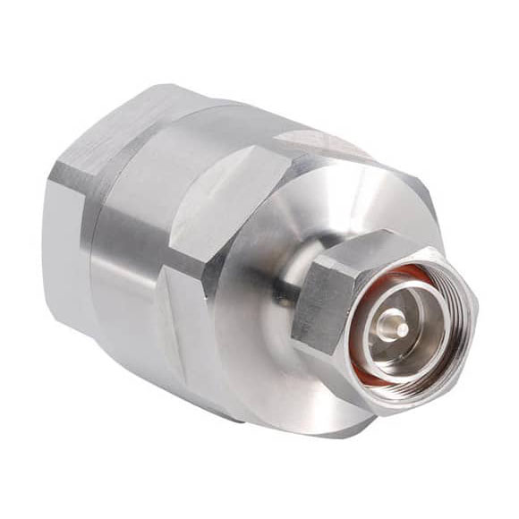

Model: TEL-4310F.78-RFC
Description
4.3-10 Female connector for 7/8″ flexible RF cable
| Material and Plating | |
| Center contact | Brass / Silver Plating |
| Insulator | PTFE |
| Body & Outer Conductor | Brass / alloy plated with tri-alloy |
| Gasket | Silicon Rubber |
| Electrical Characteristics | |
| Characteristics Impedance | 50 Ohm |
| Frequency Range | DC~3 GHz |
| Insulation Resistance | ≥5000MΩ |
| Dielectric Strength | ≥2500 V rms |
| Center contact resistance | ≤1.0 mΩ |
| Outer contact resistance | ≤1.0 mΩ |
| Insertion Loss | ≤0.1dB@3GHz |
| VSWR | ≤1.1@-3.0GHz |
| Temperature range | -40~85℃ |
| PIM dBc(2×20W) | ≤-160 dBc(2×20W) |
| Waterproof | IP67 |
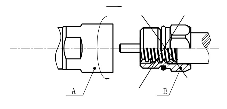
Installation Instructions of N or 7 / 16 or 4310 1 / 2″ super flexible cable
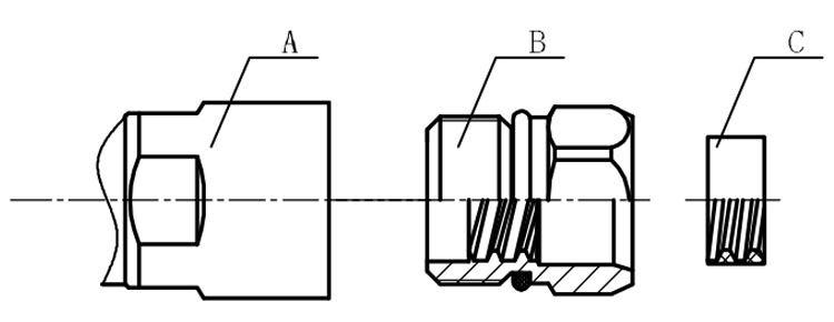
Structure of connector: ( Fig1 )
A. front nut
B. back nut
C. gasket
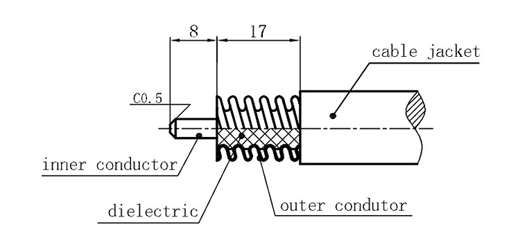
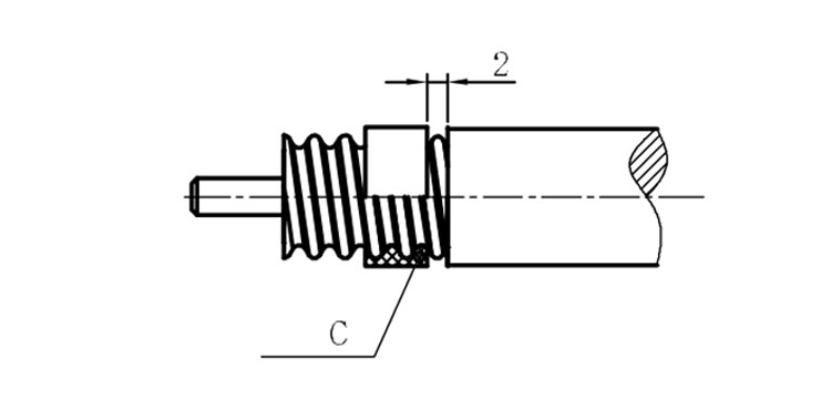
Stripping dimensions is as shown by diagram ( Fig2 ), attention should be paid while stripping:
1. The end surface of inner conductor should be chamfered.
2. Remove impurities such as copper scale and burr on the end surface of the cable.
Assembling the sealing part: Screw the sealing part in along the outer conductor of the cable as shown by the diagram ( Fig3).
Assembling the back nut (Fig3).
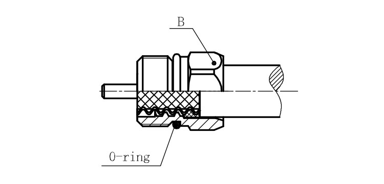
Combine the front and back nut by screwing as shown by diagram ( Figs( 5)
1. Before screwing, smear a layer of lubricating grease on the o-ring.
2. Keep the back nut and the cable motionless, Screw on main shell body on back shell body. Screw down main shell body of back shell body using monkey wrench. Assembling is finished.