Email: sales@telsto.cn
 Telephone: 86-021-6221 2832
 LinkedIn
 Youtube
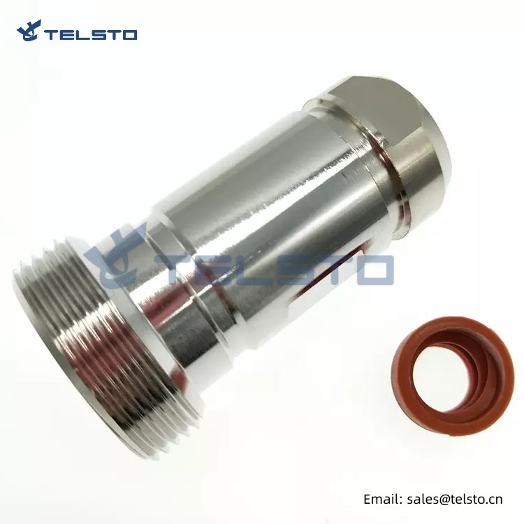
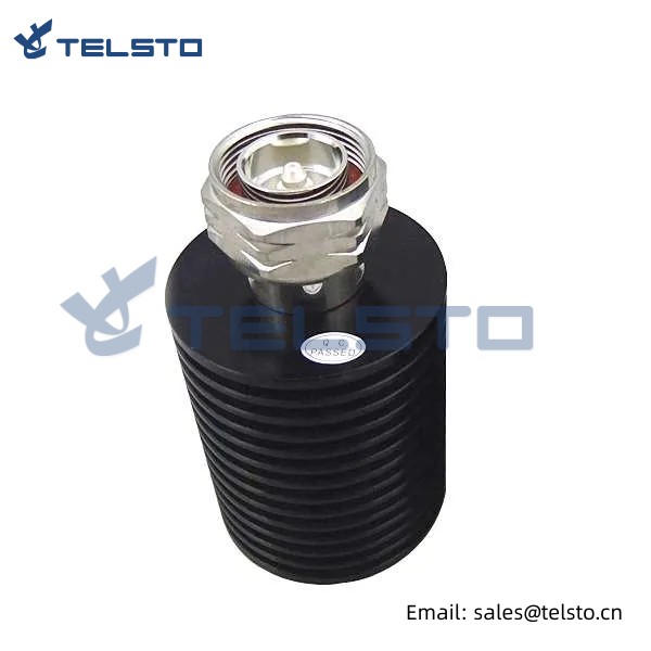
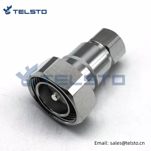
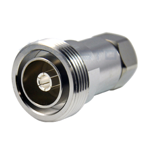
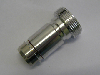
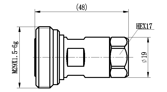
DIN Female connector for 1/2″ Super flexible RF cable
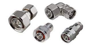
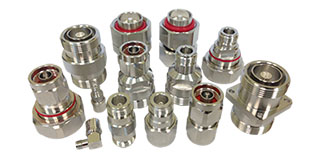
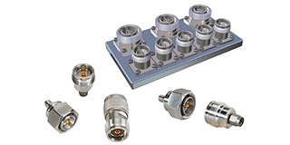
7/16 Din connector is specially designed for outdoor base stations in mobile communication (GSM, CDMA, 3G, 4G) systems, featuring high power, low loss, high operating voltage, perfect waterproof performance and applicable to various environments. It is easy to install and provides reliable connection.
Telsto 7/16 Din connectors are available in male or female gender with 50 Ohm impedance. Our 7/16 DIN connectors are available in straight or right angle versions, as well as, 4 hole flange, bulkhead, 4 hole panel or mount less options. These 7/16 DIN connector designs are available in clamp, crimp or solder attachments methods.
Features And Benefits
● Low IMD and low VSWR provides improved system performance.
● Self-flaring design ensures ease of installation with standard hand tool.
● Pres-assembled gasket protects against dust (P67) and water (IP67).
● Phosphor bronze / Ag plated contacts and Brass / Tri- Alloy plated bodies deliver a high conductivity and corrosion resistance.
Applications
● Wireless Infrastructure
● Base Stations
● Lightning Protection
● Satellite Communications
● Antenna Systems
| Interface | ||||
| According to | IEC60169-4 | |||
| Electrical | ||||
| Characteristic Impedance | 50ohm | |||
| 1 | Frequency Range | DC-3GHz | ||
| 2 | VSWR | ≤1.15 | ||
| 3 | Dielectric withstanding voltage | ≥2700V RMS,50Hz,at sea level | ||
| 4 | Dielectric Resistance | ≥10000MΩ | ||
| 6 | Contact Resistance | Outer Contact≤1.5mΩ;Center Contact≤0.4mΩ | ||
| 7 | Insertion Loss(dB) | Less than 0.15 | ||
| 8 | PIM3 | ≤-155dBc | ||
| Mechanical | ||||
| 1 | Durability | Mating cycles ≥500 | ||
| Material and plating | ||||
| Description | Material | Plating/Ni | ||
| 1 | Body | Brass | Tri-alloy | |
| 2 | Insulator | PTFE | – | |
| 3 | Center conductor | QSn6.5-0.1 | Ag | |
| 4 | Other | Brass | Ni | |
| Environmental | ||||
| 1 | Temperature Range | -40℃~+85℃ | ||
| 2 | Waterproof | IP67 | ||
Support:
* High standard quality
* Most competitive price
* Best tailored telecom solutions
* Professional, reliable and flexible services
* Strong commercial ability of solving problems
* Knowledgeable staff to hand all of your account needs
Related
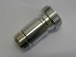
Model: TEL-DINF.12S-RFC
Description
DIN Female connector for 1/2″ Super flexible cable
| Material and Plating | |
| Center contact | Brass / Silver Plating |
| Insulator | PTFE |
| Body & Outer Conductor | Brass / alloy plated with tri-alloy |
| Gasket | Silicon Rubber |
| Electrical Characteristics | |
| Characteristics Impedance | 50 Ohm |
| Frequency Range | DC~3 GHz |
| Insulation Resistance | ≥5000MΩ |
| Dielectric Strength | 2500 V rms |
| Center contact resistance | ≤0.4 mΩ |
| Outer contact resistance | ≤0.2 mΩ |
| Insertion Loss | ≤0.15dB@3GHz |
| VSWR | ≤1.08@-3.0GHz |
| Temperature range | -40~85℃ |
| PIM dBc(2×20W) | ≤-160 dBc(2×20W) |
| Waterproof | IP67 |
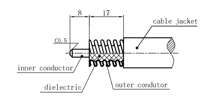
Installation Instructions of N or 7 / 16 or 4310 1 / 2″ super flexible cable
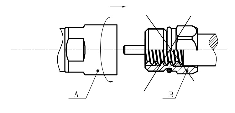
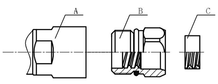
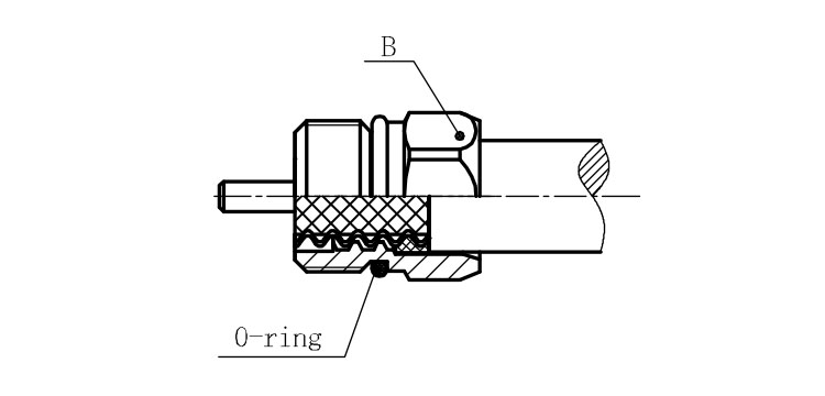
Structure of connector: ( Fig1 )
A. front nut
B. back nut
C. gasket
Stripping dimensions is as shown by diagram ( Fig2 ), attention should be paid while stripping:
1. The end surface of inner conductor should be chamfered.
2. Remove impurities such as copper scale and burr on the end surface of the cable.
Assembling the sealing part: Screw the sealing part in along the outer conductor of the cable as shown by the diagram ( Fig3).
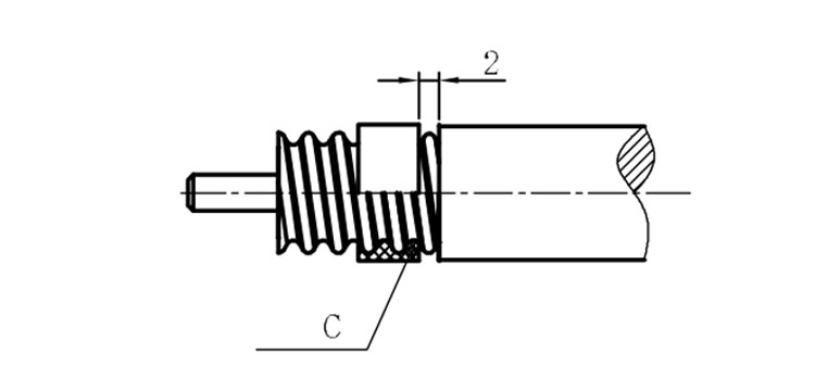
Assembling the back nut (Fig3).
Combine the front and back nut by screwing as shown by diagram ( Figs( 5)
1. Before screwing, smear a layer of lubricating grease on the o-ring.
2. Keep the back nut and the cable motionless, Screw on main shell body on back shell body. Screw down main shell body of back shell body using monkey wrench. Assembling is finished.