Email: sales@telsto.cn
 Telephone: 86-021-6221 2832
 LinkedIn
 Youtube
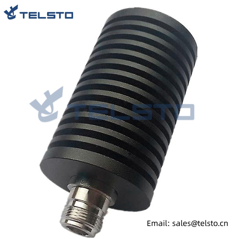
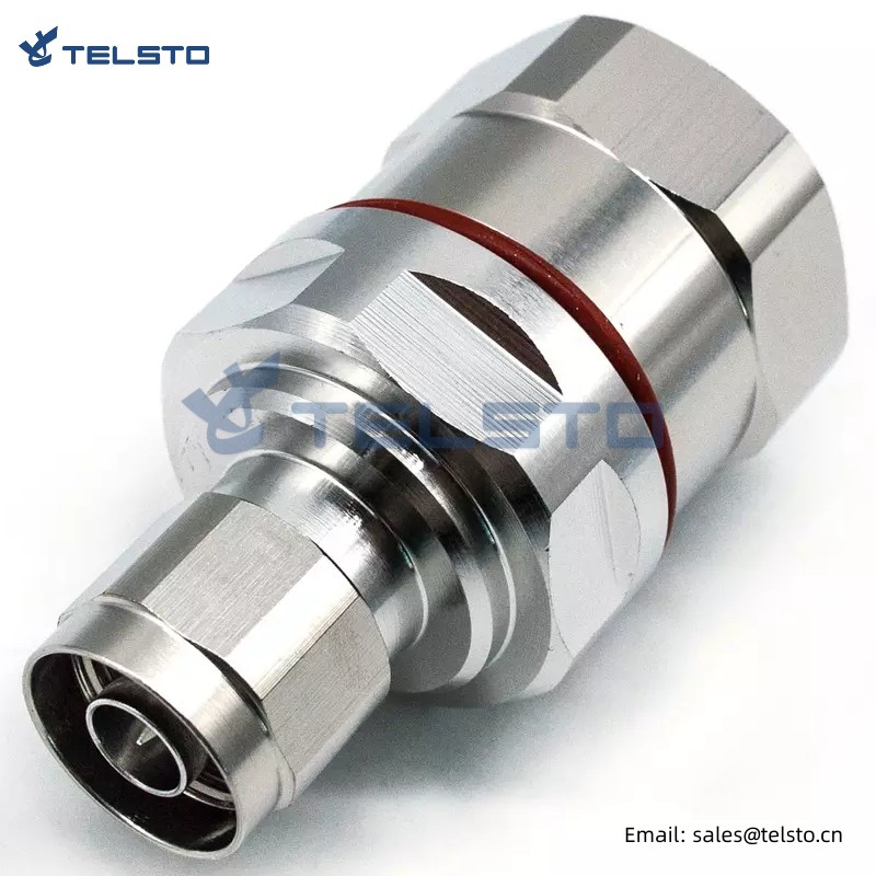
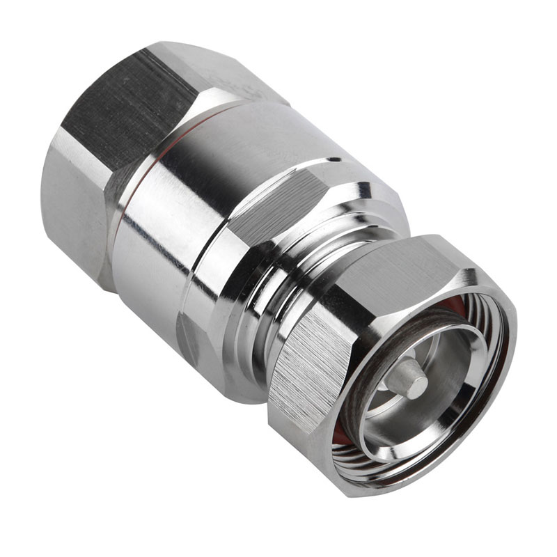
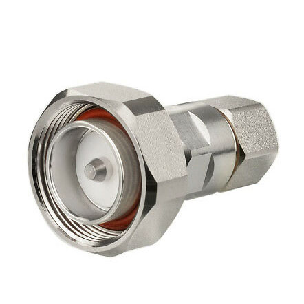
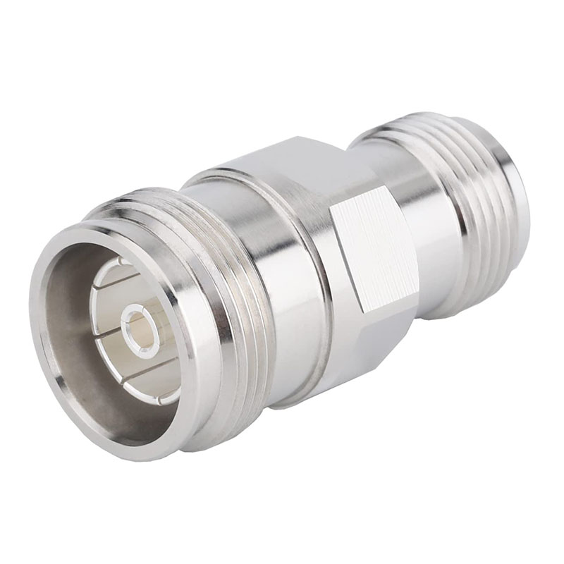
RF 7/16 Din Female Straight Connector For 7/8 Corrugated Cable
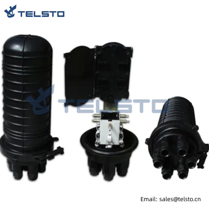
7/16 Din connector is specially designed for outdoor base stations in mobile communication (GSM, CDMA, 3G, 4G) systems, featuring high power, low loss, high operating voltage, perfect waterproof performance and applicable to various environments. It is easy to install and provides reliable connection.
Coaxial connectors are used to transmit RF signals, with a wide transmission frequency range, up to 18GHz or higher, and are mainly used for radar, communication, data transmission and aerospace equipment. The basic structure of coaxial connector includes: central conductor (male or female central contact); Dielectric materials, or insulators, which are internally and externally conductive; The outermost part is the external contact, which plays the same role as the outer shielding layer of the shaft cable, that is, transmitting signals and acting as the grounding element of the shield or circuit. RF coaxial connectors can be divided into many types. The following is a summary of common types.

Features And Benefits
● Low IMD and low VSWR provides improved system performance.
● Self-flaring design ensures ease of installation with standard hand tool.
● Pre-assembled gasket protects against dust (P67) and water (IP67).
● Phosphor bronze / Ag plated contacts and Brass / Tri- Alloy plated bodies deliver a high conductivity and corrosion resistance.

Applications
● Wireless Infrastructure
● Base Stations
● Lightning Protection
● Satellite Communications
● Antenna Systems

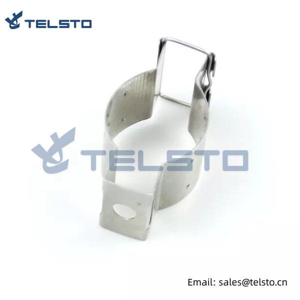
7/16 din female jack clamp rf coaxial connector for 7/8" cable
| Temperature Range | -55℃~+155℃ |
| Frequency Range | DC ~7.5GHz |
| Impedance | 50 Ω |
| Working Voltage | 2700 V r.m.s , at sea level |
| Vibration | 100 m/S2 (10-~500Hz), 10g |
| Salt spray teste | 5% NaCl solution; test time≥48h |
| Waterproof Sealing | IP67 |
| Withstanding Voltage | 4000 V r.m.s,at level sea |
| Contact Resistance | |
| Center contact | ≤0.4 MΩ |
| Outer contact | ≤1.5MΩ |
| Insulation Resistance | ≥10000 MΩ |
| Center Conductor Retention Force | ≥6 N |
| Engagement forcey | ≤45N |
| Insertion Loss | 0.12dB/3GHz |
| V.S.W.R | |
| Straight | ≤1.20/6GHz |
| Right angle | ≤1.35/6GHz |
| Shielding power | ≥125dB/3GHz |
| Average power | 1.8KW/1GHz |
| Durability(matings) | ≥500 |
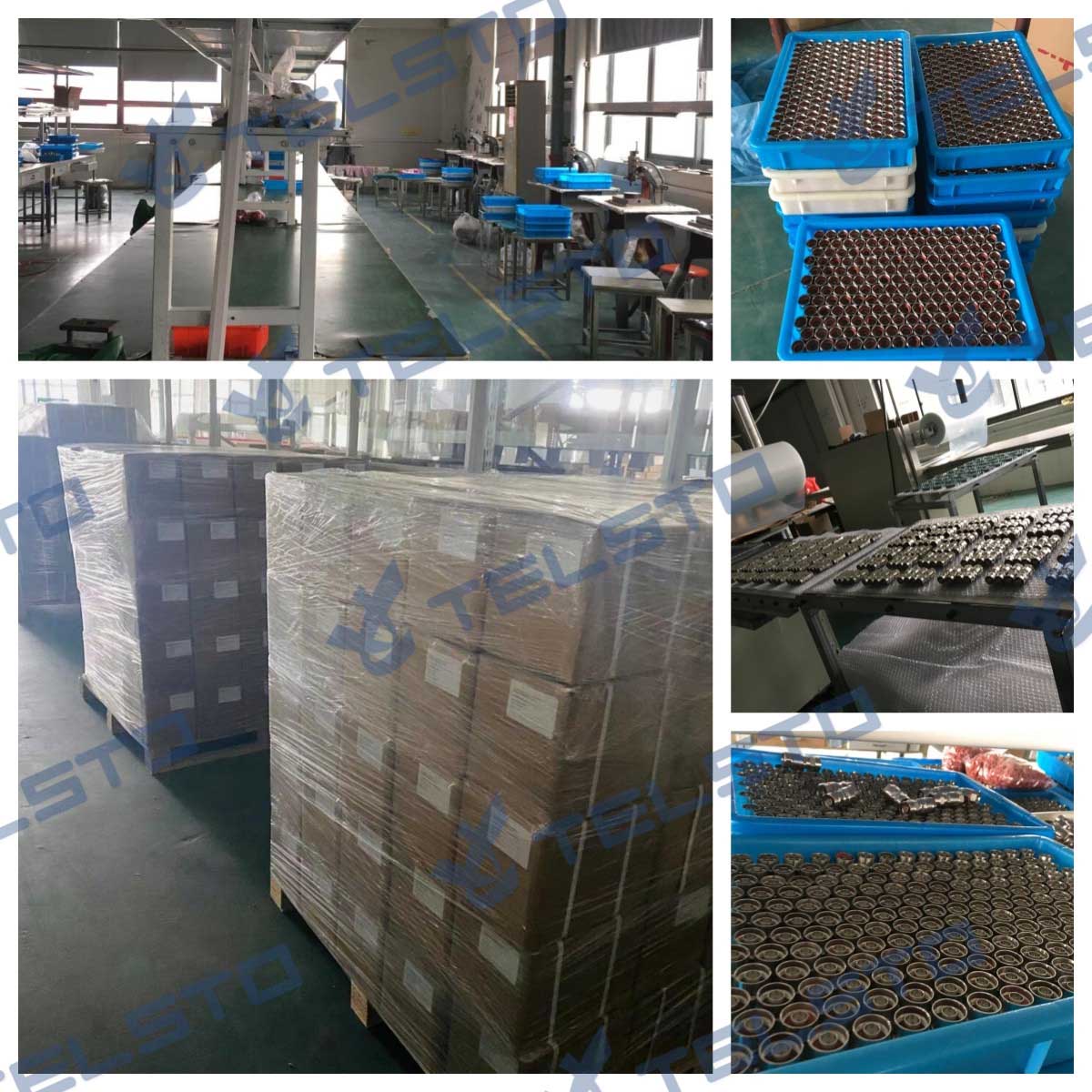
Packaging & Shipping
Packaging Details: The connectors will be packed in one small bag and then put in one box.
If you need custom package, we will do as your request.
Delivery time: Around a week.
1. We focus on RF Connector & RF Adapter &Cable Assembly &Antenna.
2. We have a vigorous and creative R&D team with the fullest mastery of the core technology.
We commit ourselves to the development of high performance connector production, and dedicate ourselves to achieving a leading position in connector innovation and production.
3. Our custom RF cable assemblies are built-in and shipped worldwide.
4. RF cable assemblies can be produced with many different connector types and custom lengths depending on your needs and applications
5. Special RF Connector ,RF Adapter or RF Cable assembly could be customized.
Related
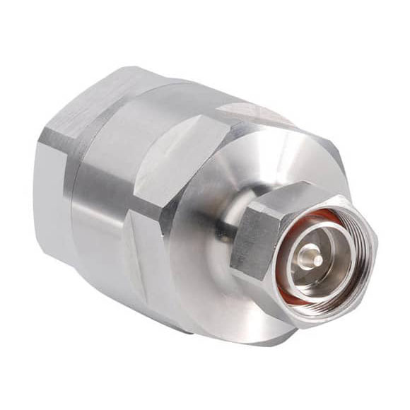
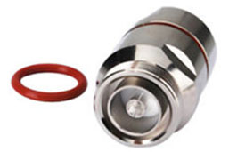
Model: TEL-DINF.78-RFC
Description
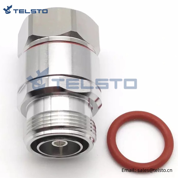
DIN 7/16 Female connector for 7/8″ flexible cable
| Material and Plating | |
| Center contact | Brass / Silver Plating |
| Insulator | PTFE |
| Body & Outer Conductor | Brass / alloy plated with tri-alloy |
| Gasket | Silicon Rubber |
| Electrical Characteristics | |
| Characteristics Impedance | 50 Ohm |
| Frequency Range | DC~3 GHz |
| Insulation Resistance | ≥5000MΩ |
| Dielectric Strength | 4000 V rms |
| Center contact resistance | ≤0.4mΩ |
| Outer contact resistance | ≤0.2 mΩ |
| Insertion Loss | ≤0.1dB@3GHz |
| VSWR | ≤1.06@3.0GHz |
| PIM dBc(2×20W) | ≤-160 dBc(2×20W) |
| Electrical Characteristics | Electrical Characteristics |
| Interface Durability | 500 cycles |
| Interface Durability Method | 500 cycles |
| Interface Durability Method | According to IEC 60169:16 |
| 2011/65EU(ROHS) | Compliant |
| Temperature range | -40~85℃ |
| Waterproof | IP67 |
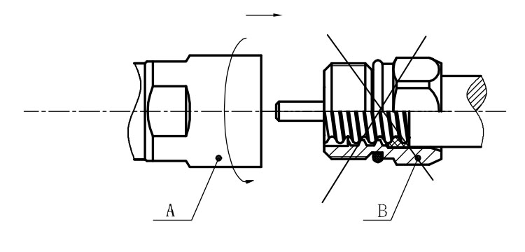
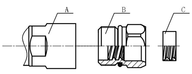
Installation Instructions of N or 7 / 16 or 4310 1 / 2″ super flexible cable
Structure of connector: ( Fig1 )
A. front nut
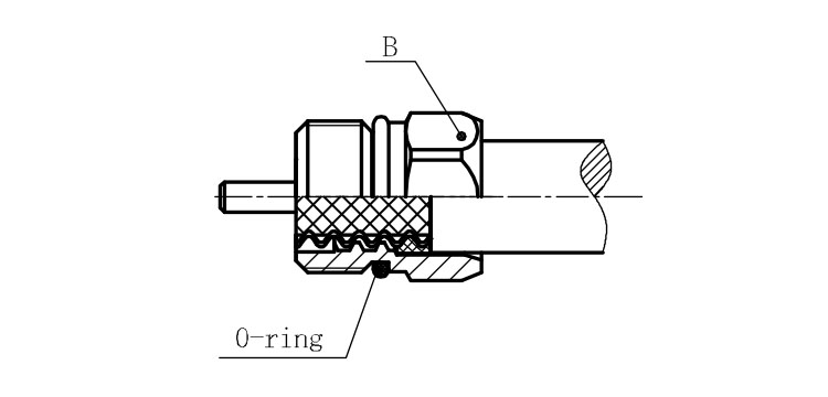
B. back nut
C. gasket
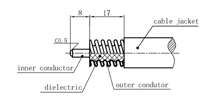
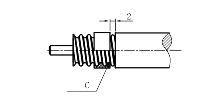
Stripping dimensions is as shown by diagram ( Fig2 ), attention should be paid while stripping:
1. The end surface of inner conductor should be chamfered.
2. Remove impurities such as copper scale and burr on the end surface of the cable.
Assembling the sealing part: Screw the sealing part in along the outer conductor of the cable as shown by the diagram ( Fig3).
Assembling the back nut (Fig3).
Combine the front and back nut by screwing as shown by diagram ( Figs( 5)
1. Before screwing, smear a layer of lubricating grease on the o-ring.
2. Keep the back nut and the cable motionless, Screw on main shell body on back shell body. Screw down main shell body of back shell body using monkey wrench. Assembling is finished.