Email: sales@telsto.cn
 Telephone: 86-021-6221 2832
 LinkedIn
 Youtube
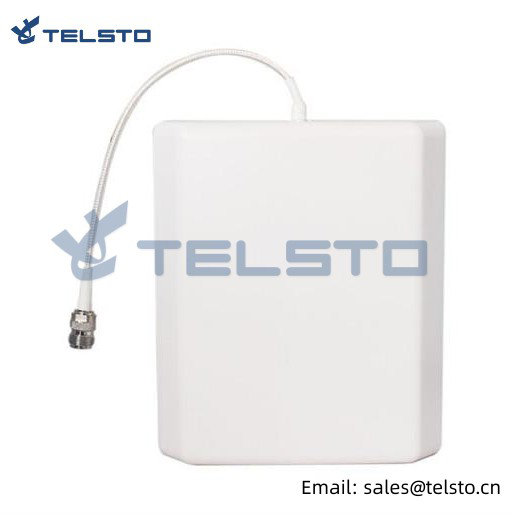
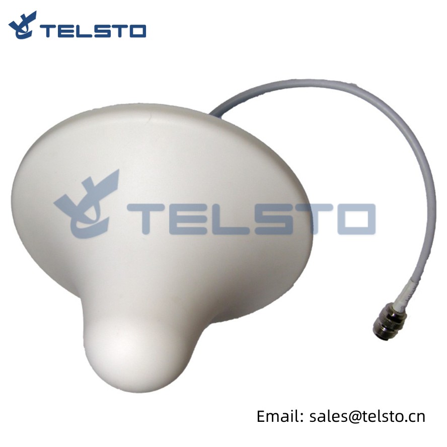
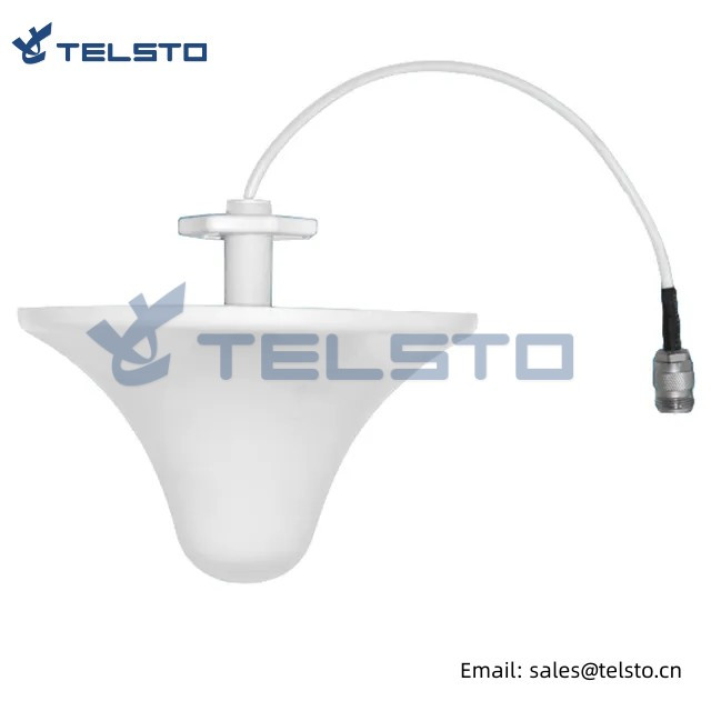
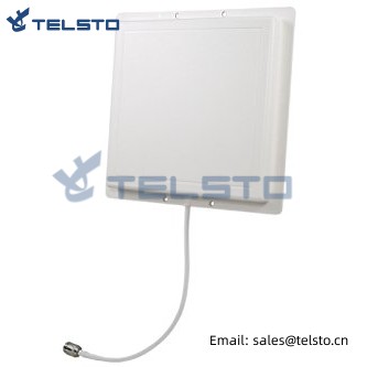
Indoor Directional Antenna
Feature: Exquisite appearance Good impact resistance, waterproof and anti corrosion ability Standard installing mount kits packages for holding pole Optimized dimension Designed with wide band technology, medium gain, low standing wave ratio
Application: GSM/ CDMA/ DCS/ PCS/ 3G/ 4G/ LTE/ WLAN/ Wi-Fi system
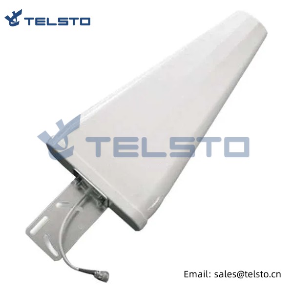
Follow these procedures to install antenna with holding pole, adjust tilt angle of antenna, tighten bolts, screws and nuts. (1) L shape mounting kits should be aligned antenna bolt, put on flat washer, spring hook, screw cap in turn, then locked nut. (2) U shape threaded rod of M6 passed serrated and L shape mounting kits, held antenna with dia. 35-50mm pole, then locked nut. (3) In order to get the best signal, adjusted pitching angle of antenna via the hole position of L shape mounting kit, then locked all nuts and sealed antenna connector end. (4) The height of erection should be more than 3 meters from base level, also nearby regions of erection have not tall buildings and larger metals. In a word, open-sided land.
| Mechanical Specifications | |
| Dimensions | 210x180x44mm |
| Weight | 0.6Kg |
| Radiator Material | Silver-plated Brass |
| Radome Material | ABS |
| Radome Color | Ivory-white |
| Operational Humidity | < 95% |
| Operating temperature | -40~55 ℃ |
| Electrical Specifications | |
| Frequency Range | 806-960MHz 1710~2300MHz 2300-2700MHz |
| Gain | 7dBi 8 dBi 9dBi |
| VSWR | ≤1.5 |
| Polarization | Vertical |
| Horizontal beam width | 90 70 70 |
| Vertical beam width | 65 60 60 |
| IMD3, dBc @+ 33dBm | ≤-140 |
| Input Impedance | 50Ω |
| Max Input Power | 50W |
| Connector | N Female |
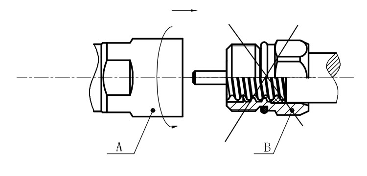
Installation Instructions of N or 7 / 16 or 4310 1 / 2″ super flexible cable
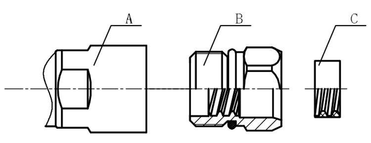
Structure of connector: ( Fig1 )
A. front nut
B. back nut
C. gasket
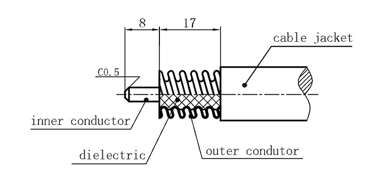
Stripping dimensions is as shown by diagram ( Fig2 ), attention should be paid while stripping:
1. The end surface of inner conductor should be chamfered.
2. Remove impurities such as copper scale and burr on the end surface of the cable.
Assembling the sealing part: Screw the sealing part in along the outer conductor of the cable as shown by the diagram ( Fig3).
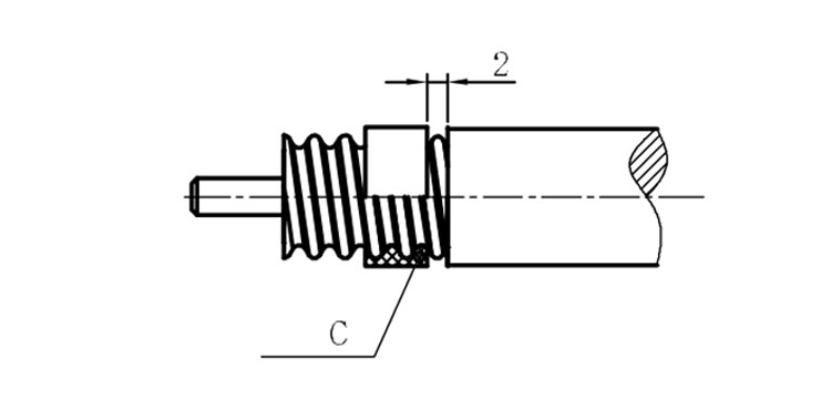
Assembling the back nut (Fig3).
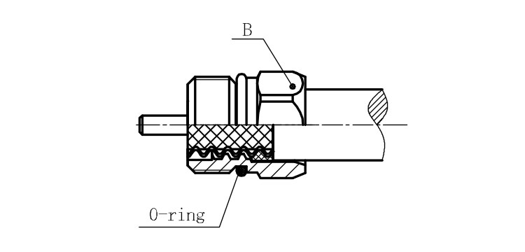
Combine the front and back nut by screwing as shown by diagram ( Figs( 5)
1. Before screwing, smear a layer of lubricating grease on the o-ring.
2. Keep the back nut and the cable motionless, Screw on main shell body on back shell body. Screw down main shell body of back shell body using monkey wrench. Assembling is finished.