Email: sales@telsto.cn
 Telephone: 86-021-6221 2832
 LinkedIn
 Youtube

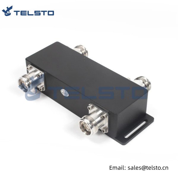
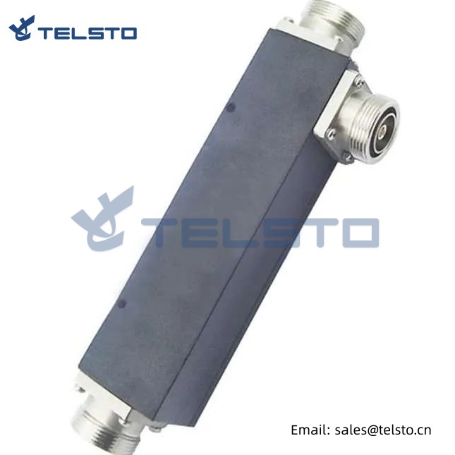
Wide-Band Directional Coupler 698-2700MHz N
Telsto Wide band Directional couplers provide flat coupling of one signal path to another in one direction only (known as directive). They commonly consist of an auxiliary line coupling electrically to a main line. One end of the auxiliary line is permanently fitted with a matched termination. Directive (the difference between coupling in one direction compared to the other) is approximately 20 dB for couplers, Directional couplers are used whenever part of a signal needs to be separated off or two signals need to be combined. Telsto offers narrow band and wireless band directional couplers with coupling ranging from 3 dB to 50 dB or more.
| General Specification |
TEL-MBDC-698-2700 N |
||||||||
| Frequency Range (MHz) |
698-2700 |
||||||||
| Coupling(dB)* |
5 |
6 |
7 |
8 |
10 |
15 |
20 |
25 |
30 |
| Coupling uniform(dB) |
±0.8 |
±0.8 |
±0.8 |
±0.8 |
±1.0 |
±1.0 |
±1.0 |
±1.0 |
±1.0 |
| VSWR |
≤1.25 |
||||||||
| Insertion Loss(dB) |
≤2.0 |
≤1.6 |
≤1.35 |
≤1.1 |
≤0.7 |
≤0.4 |
≤0.3 |
≤0.2 |
≤0.2 |
| Directivity(dB) |
≥20 |
||||||||
| Isolation between ports(dB) |
≥25 |
≥26 |
≥27 |
≥28 |
≥30 |
≥35 |
≥40 |
≥45 |
≥50 |
| PIM3(dBc) |
≤-155(@+43dBm×2) |
||||||||
| Impedance (Ω) |
50 |
||||||||
| Power Rating(W) |
200 |
||||||||
| Connector |
N-F |
||||||||
| Application Circumstance |
IP65 |
||||||||
| Temperature Range(℃) |
-35-+70 |
||||||||
Installation Instructions of N or 7 / 16 or 4310 1 / 2″ super flexible cable
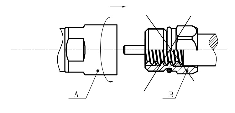
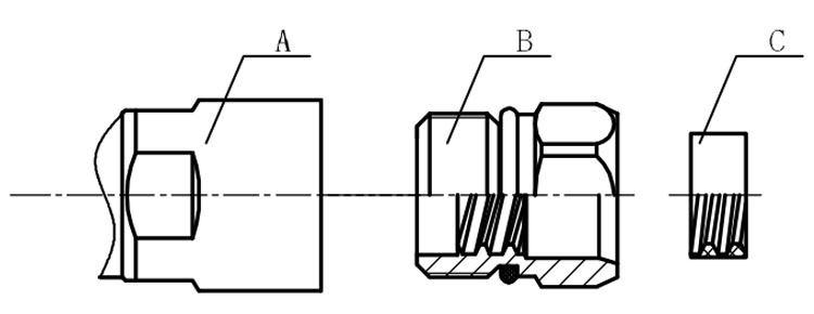
Structure of connector: ( Fig1 )
A. front nut
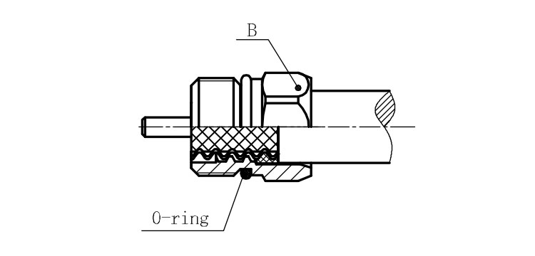
B. back nut
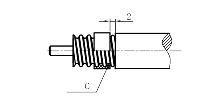
C. gasket
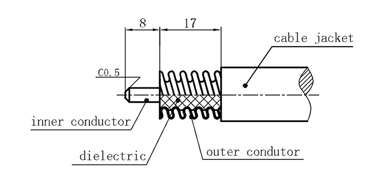
Stripping dimensions is as shown by diagram ( Fig2 ), attention should be paid while stripping:
1. The end surface of inner conductor should be chamfered.
2. Remove impurities such as copper scale and burr on the end surface of the cable.
Assembling the sealing part: Screw the sealing part in along the outer conductor of the cable as shown by the diagram ( Fig3).
Assembling the back nut (Fig3).
Combine the front and back nut by screwing as shown by diagram ( Figs( 5)
1. Before screwing, smear a layer of lubricating grease on the o-ring.
2. Keep the back nut and the cable motionless, Screw on main shell body on back shell body. Screw down main shell body of back shell body using monkey wrench. Assembling is finished.