Email: sales@telsto.cn
 Telephone: 86-021-6221 2832
 LinkedIn
 Youtube
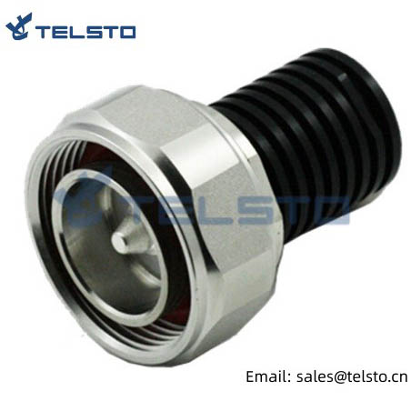

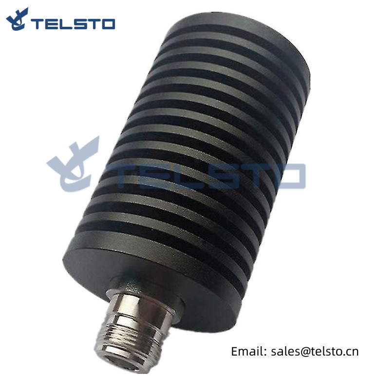
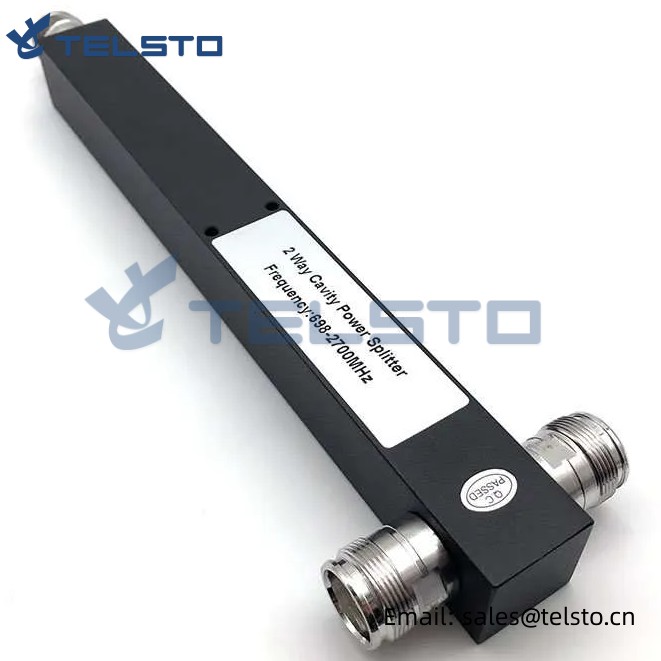
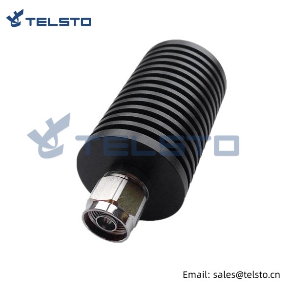
2 Watt Din Type Coaxial Dummy Load Termination
RF load / termination (also known as a dummy load) is just part of a wide selection of coaxial terminator products supplied for radio, antenna and other types of RF components for typical use, production, laboratory test and measurement, defense / military, etc. which are specifically made ready for quick shipment. Our coaxial radio frequency load termination is manufactured in a RF load design with N/Din connectors.
Termination loads absorb RF & microwave energy and are commonly used as dummy loads of antenna and transmitter. They are also used as match ports in many multi port microwave device such as circulation and directional couple to make these ports which are not involved in the measurement be terminated in their characteristic impedance in order to ensure an accurate measurement.
Model No. TEL-TL-DINM2W
Electrical Characteristic Impedance 50ohm
Frequency Range DC-3GHz
VSWR ≤1.15
Power Capacity 2Watt
RF Connector Din Male Connector
Connector body: Brass Tri-Metal(CuZnSn)
Insulator: PTFE
Inner Conductor: Phosphor Bronze Ag
Housing Aluminum Black Passivization
Environmental
Operating Temp. _45~ 85 ℃
Storage Temp. _60~120℃
Weatherproof Rate IP65
Relative Humidity 5%-95%
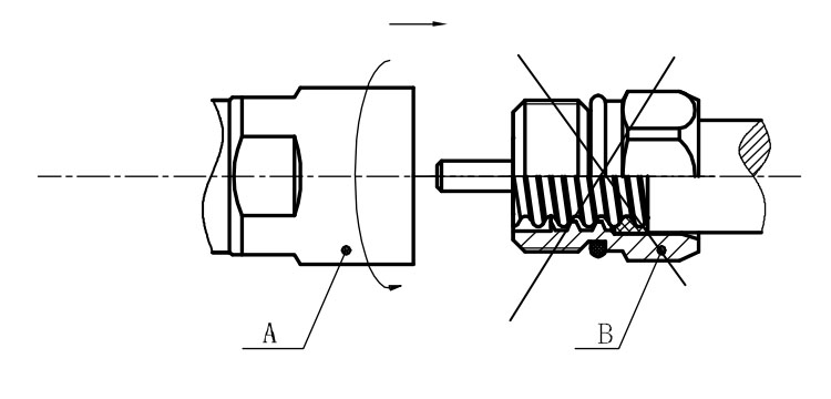
Installation Instructions of N or 7 / 16 or 4310 1 / 2″ super flexible cable
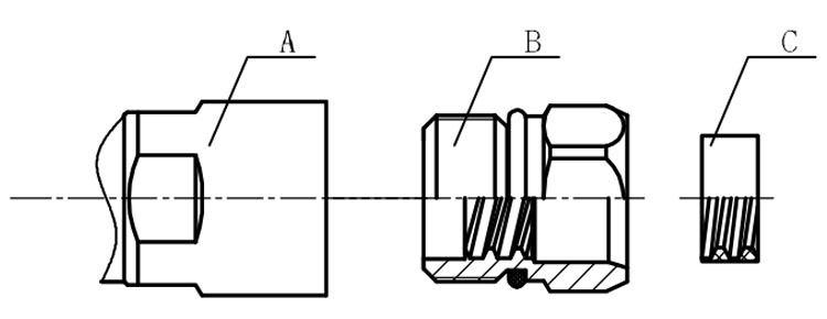
Structure of connector: ( Fig1 )
A. front nut
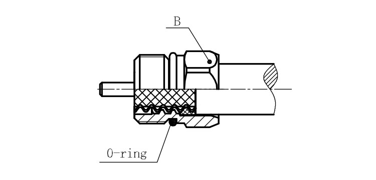
B. back nut
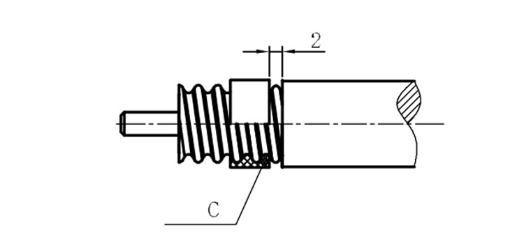
C. gasket
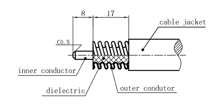
Stripping dimensions is as shown by diagram ( Fig2 ), attention should be paid while stripping:
1. The end surface of inner conductor should be chamfered.
2. Remove impurities such as copper scale and burr on the end surface of the cable.
Assembling the sealing part: Screw the sealing part in along the outer conductor of the cable as shown by the diagram ( Fig3).
Assembling the back nut (Fig3).
Combine the front and back nut by screwing as shown by diagram ( Figs( 5)
1. Before screwing, smear a layer of lubricating grease on the o-ring.
2. Keep the back nut and the cable motionless, Screw on main shell body on back shell body. Screw down main shell body of back shell body using monkey wrench. Assembling is finished.