Email: sales@telsto.cn
 Telephone: 86-021-6221 2832
 LinkedIn
 Youtube
Telsto RF load terminations
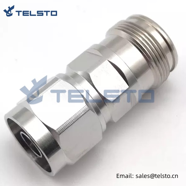
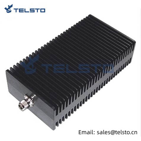
Telsto RF load terminations are constructed of an aluminum finned heat sink, brass nickel plated or stainless steel,they are of good low PIM performance.
Termination loads absorb RF & microwave energy and are commonly used as dummy loads of antenna and transmitter. They are also used as match ports in many multi port microwave device such as circulation and directional couple to make these ports which are not involved in the measurement be terminated in their characteristic impedance in order to ensure an accurate measurement.
Termination loads, also call dummy loads, are the passive 1-port interconnect devices, which provide a resistive power termination to properly terminate the output port of a device or to terminate one end of an RF cable. Telsto Termination loads are characterized by low VSWR, high power capacity and performance stability. Widely used for DMA/GMS/DCS/UMTS/WIFI/WIMAX etc.
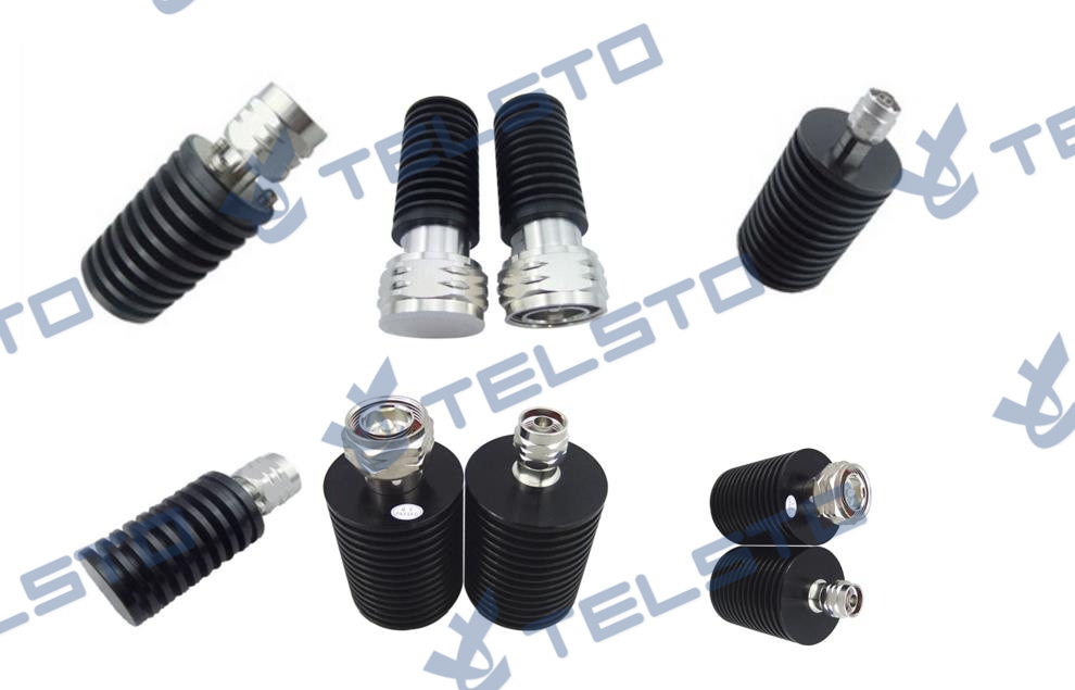
| Product | Description | Part No. |
| Termination Load | N Male / N Female, 2W | TEL-TL-NM/F2W |
| N Male / N Female, 5W | TEL-TL-NM/F5W | |
| N Male / N Female, 10W | TEL-TL-NM/F10W | |
| N Male / N Female, 25W | TEL-TL-NM/F25W | |
| N Male / N Female, 50W | TEL-TL-NM/F50W | |
| N Male / N Female, 100W | TEL-TL-NM/F100W | |
| DIN Male / Female, 10W | TEL-TL-DINM/F10W | |
| DIN Male / Female, 25W | TEL-TL-DINM/F25W | |
| DIN Male / Female, 50W | TEL-TL-DINM/F50W | |
| DIN Male / Female, 100W | TEL-TL-DINM/F100W |
FAQ
1. What is the termination/dummy load?
Termination/dummy load is a resistive component that absorbs all the output power of an electrical generator or radio transmitter in order to simulate working conditions for test purposes.
2. What is the function of termination/dummy load?
a. To test a radio transmitter, it acts as a protector to be a substitute of antenna.
50ohm dummy load provides proper resistance at final RF amplifier stage.
b. To prevent away from other radios interference when adjusting and testing the transmitted.
c. To be a replacement of the loudspeaker during audio amplifier testing.
d. To be used in the isolated port in a directional couple and the unused port of a power divider.
3. How to choose a dummy load and the important parameters?
a. Frequency: DC-3GHz
b. Power handling capacity: 200W
c. VSWR: ≤1.2, means it is good
d. IP Grade: IP65 means this dummy load can be used outdoor, well dust proofing and waterproofing.
e. RF Connector: N-Male (or other connector type available)
Customized manufacture available
We are able to provide 1W, 2W, 5W, 10W, 15W, 20W, 25W, 30W, 50W, 100W, 200W, 300W, 500W RF Dummy Load. The Frequency can reach DC-3G, DC-6G, DC-8G, DC-12.4G, DC-18G, DC-26G, DC-40G. RF Connectors can be N-type, SMA-type, DIN-type, TNC-type and BNC-type per your requirements.
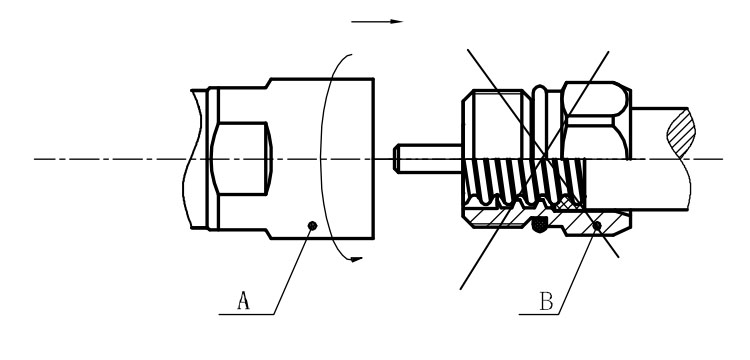
Installation Instructions of N or 7 / 16 or 4310 1 / 2″ super flexible cable
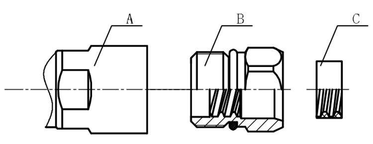
Structure of connector: ( Fig1 )
A. front nut
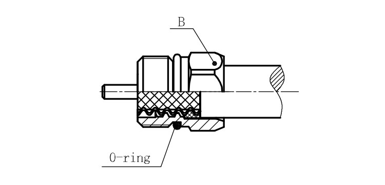
B. back nut
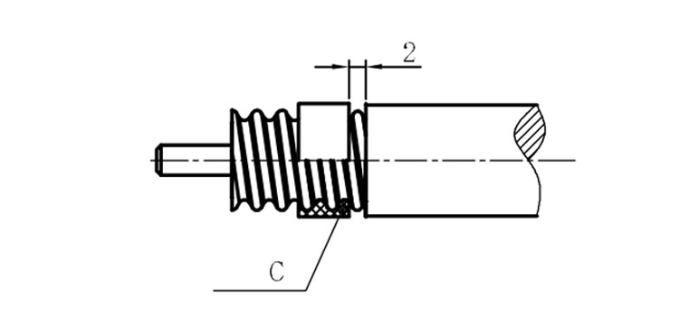
C. gasket
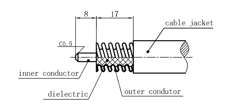
Stripping dimensions is as shown by diagram ( Fig2 ), attention should be paid while stripping:
1. The end surface of inner conductor should be chamfered.
2. Remove impurities such as copper scale and burr on the end surface of the cable.
Assembling the sealing part: Screw the sealing part in along the outer conductor of the cable as shown by the diagram ( Fig3).
Assembling the back nut (Fig3).
Combine the front and back nut by screwing as shown by diagram ( Figs( 5)
1. Before screwing, smear a layer of lubricating grease on the o-ring.
2. Keep the back nut and the cable motionless, Screw on main shell body on back shell body. Screw down main shell body of back shell body using monkey wrench. Assembling is finished.